Positioning and buffering device for artificial knee joint

a buffering device and knee joint technology, applied in artificial legs, prostheses, medical science, etc., can solve the problems of inconvenient walking down hill or down a slope for the disabled, and the inability to absorb impact for

Inactive Publication Date: 2006-05-16
CHENG CHIA PAO
View PDF7 Cites 125 Cited by
  • Summary
  • Abstract
  • Description
  • Claims
  • Application Information

AI Technical Summary

Benefits of technology

[0006]Yet another object of the present invention is to provide a positioning and buffering device for artificial knee joint, wherein when the knee joint is bent backward or standing, a pressure exerted to change the interlinking rod and the angle of the interlinking rod such that the knee joint is at a positioning state and the shank will not bend or at a risky position.
[0007]A further object of the present invention is to provide a positioning and buffering device for artificial knee joint, wherein when walking on a slope the knee joint can be bent at certain angle and the buffering device produces a buffering and absorbing effect.

Problems solved by technology

However, when walking down a sloping ground, a small angle is formed and the absorbing of impact force cannot be effected.
This is due to the fact that the interlinking rod cannot be positioned.
When walking down hill or down a sloping ground, the interlinking rod of the knee joint bends suddenly or knees dangerously, and therefore it is not convenient for the disable to walk down hill or down a slope.

Method used


Image

  • Positioning and buffering device for artificial knee joint
  • Positioning and buffering device for artificial knee joint
  • Positioning and buffering device for artificial knee joint

Examples


Embodiment Construction

[0019]The following descriptions are of exemplary embodiments only, and are not intended to limit the scope, applicability or configuration of the invention in any way. Rather, the following description provides a convenient illustration for implementing exemplary embodiments of the invention. Various changes to the described embodiments may be made in the function and arrangement of the elements described without departing from the scope of the invention as set forth in the appended claims.

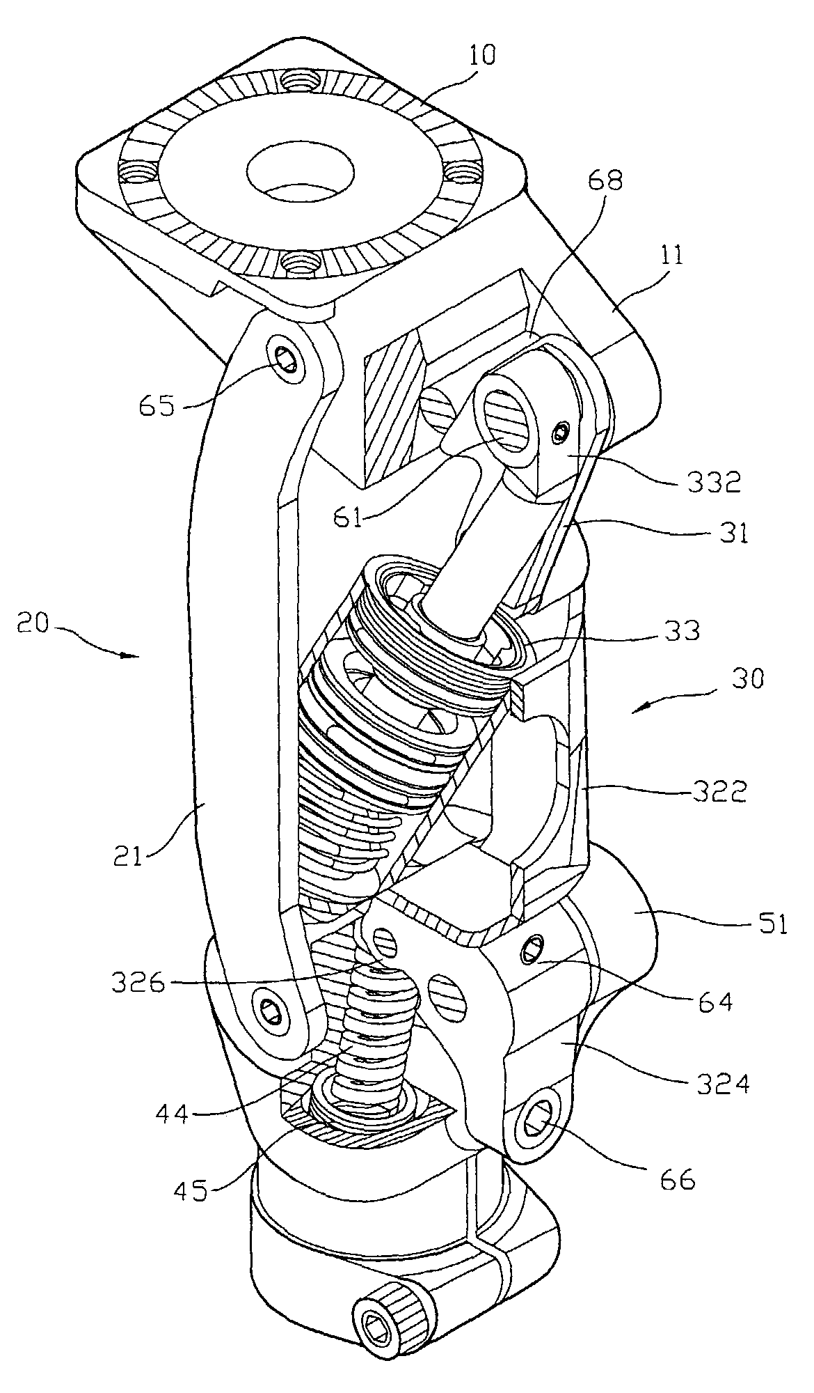
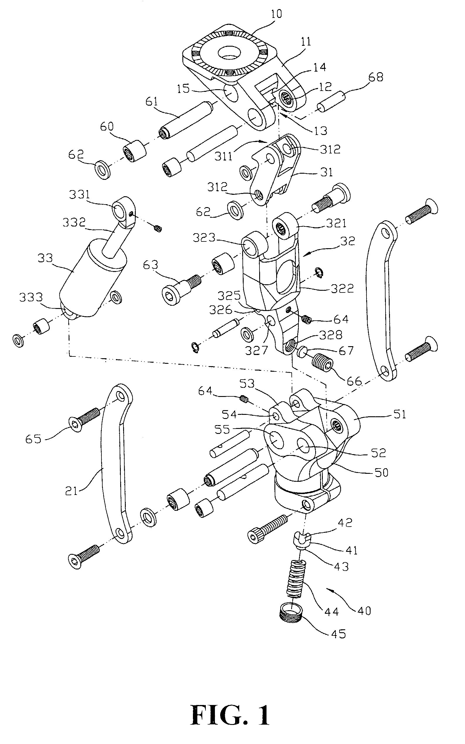
[0020]Referring to FIG. 1, the positioning and buffering device of an artificial knee joint comprises a knee cap head 10, an interlinking device 20 (arch plates 21), a buffering device 30 (interlinking rod 31), interlinking support 32, hydraulic cylinder 33), a spring device 40 (spring support 42, spring 44), and a knee cap body 50. The knee cap head is connected upward to the thigh and the lower edge of the knee cap body is used to connect to the shank and the leg bottom portion.

[0021]In accorda...


PUM


Abstract

A positioning and buffering device of a knee joint for artificial limb is disclosed. The device comprises a knee cap head, an interlinking device including two arch plates, a buffering device including an interlinking rod, an interlinking support and a hydraulic cylinder; a spring device having a spring and a spring support; and a knee cap body module. The knee cap body is used to connect to the thigh and the lower edge of the knee cap body is for connection to the shank and the leg bottom portion. By means of the interlinking rod and the linking support, when the leg is stretched or is standing, a pressure exerted changes the angle between the interlinking rod and the interlinking support such that the knee joint is at a fixed position, the shank will not bent or knee down and the buffering device will produce a buffering and shock absorbing effect.

Description

BACKGROUND OF THE INVENTION[0001](a) Technical Field of the Invention[0002]The present invention relates to a positioning and buffering device for artificial knee joint, and in particular, to a device provided with interlinking rod and support, in the course of the moving of the knee joint within a predetermined angle, absorbing impact force exerted onto the knee joint.[0003](b) Description of the Prior Art[0004]Artificial limbs and joints allow a disable to walk normally. These joints, for instance a knee joint, have an interlinking rod mounted with a pad. When the knee joint is stretched to touch the ground an impact force is exerted. This will press the pad so as to absorb the impact. However the absorbing of shock is a straight line direction of the leg portion and the knee joint, and when walking along a flat ground, the leg can be stretched straight to allow the impact force to be absorbed. However, when walking down a sloping ground, a small angle is formed and the absorbing ...

Claims


Application Information

Patent Timeline
Patent Type & Authority Patents(United States)
IPC IPC(8): A61F2/64A61F2/68
CPCA61F2/644A61F2/68A61F2/60A61F2/80A61F2002/745A61F2002/503A61F2002/5073A61F2002/6614A61F2002/5007A61F2/74
Inventor CHENG, CHIA PAO
Owner CHENG CHIA PAO
Why Eureka
Try Eureka