Snap locking angle adjustable device, in particular a carpenter's square

a carpenter's square and adjustable technology, applied in the direction of couplings, printing, instruments, etc., can solve the problems of blade and handle snapping lock, difficult to fabricate the square with maintained angle precision, and thinner metal bridge between neighbouring holes

Active Publication Date: 2006-05-23
LOGOSOL
View PDF36 Cites 31 Cited by
  • Summary
  • Abstract
  • Description
  • Claims
  • Application Information

AI Technical Summary

Problems solved by technology

However, compared to holes, this would yield much thinner metal bridges between neighbouring holes—much thinner, because the holes are positioned in a row along a circle with a radius that can not be much larger than 15 mm, and because the holes have a certain feasible minimum diameter—thus causing difficulties to fabricate the square with maintained angle precision.
At certain angles between the handle and the blade, the steel balls align with the holes, causing the blade and the handle to snap lock.

Method used


Image

  • Snap locking angle adjustable device, in particular a carpenter's square
  • Snap locking angle adjustable device, in particular a carpenter's square
  • Snap locking angle adjustable device, in particular a carpenter's square

Examples


first embodiment

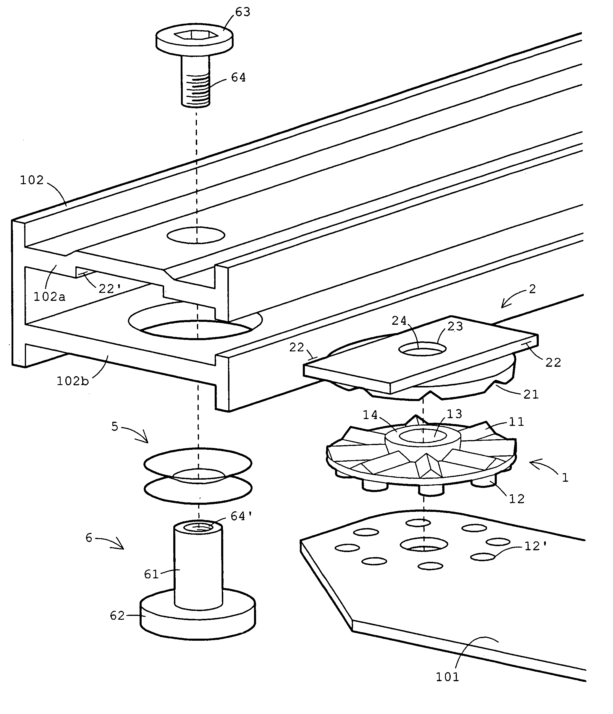
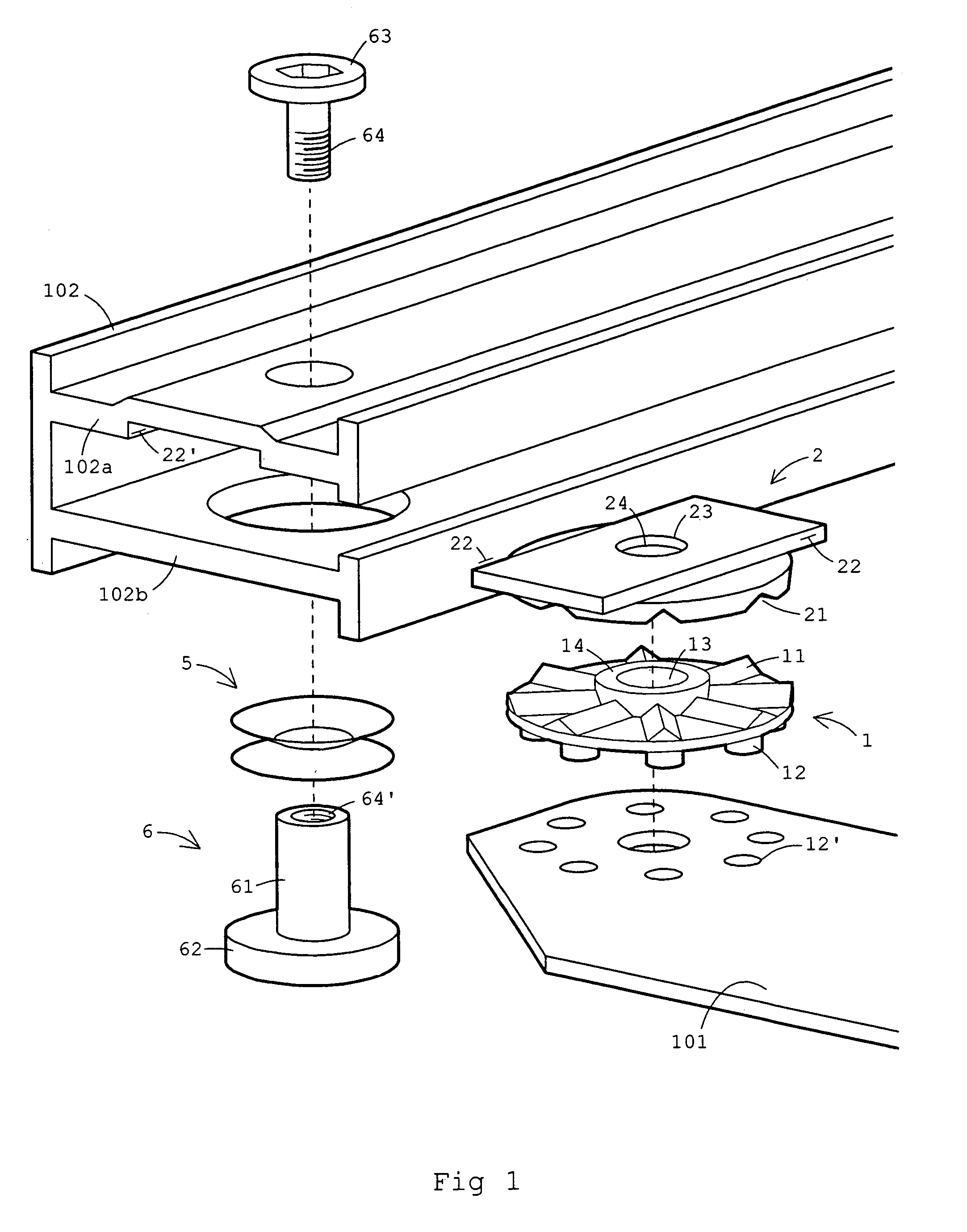
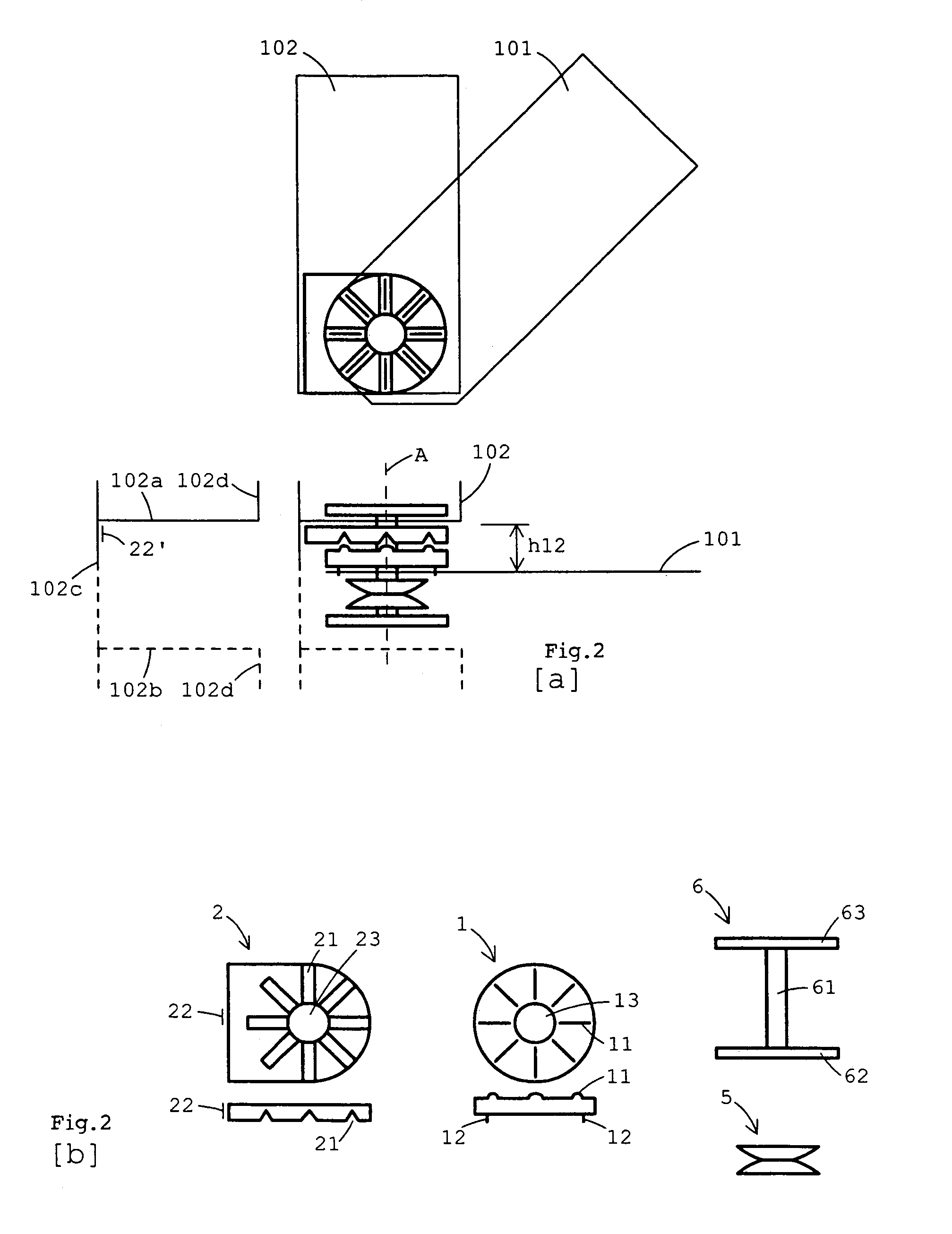
[0072]An embodiment of the invention is illustrated by an exploded view in FIG. 1 and by a schematic drawing in FIGS. 2a and 2b. Consider first the plate (1) in FIG. 1: the plate has ridges (11) on its upper face and pins (12) on its lower face. Assembled, the pins (12) fit tightly in the holes (12′), thus securing the plate (1) to the blade (101). Next, consider the plate (2): this plate has grooves (21) on its bottom face and a rectangular body with edges (22) on its upper face. Assembled, the rectangular body with the edges (22) fits tightly in the channel with the walls (22′), thus securing the plate (2) to the handle (102). Now, the plate (2) may put on top of the plate (1) in a manner such that the ridges (11) mate with the grooves (21). Assembled, the elements (5, 101, 1, 2, 102a) forms a sandwich squeezed between the heads (62) and (63). This is schematically shown in FIG. 2a. The upper screw (63, 64) and the lower, internal threaded, screw (61, 62, 64′) are tightened togeth...

second and third embodiments

[0073]Two other embodiments are illustrated in FIGS. 3a and 3b. First, as a matter of notation, the graphic symbols for the elements (5), (1), (2), (62), and (63) are the same as in FIG. 2b. Now, the embodiment shown in FIG. 3a is characterized in that the components (102b, 5, 101, 1, 2, 102a) forms a sandwich squeezed between the heads (62) and (63). Notice further that, because the spring washers rest upon the lower face (102b) of the handle, the hole in (102b) can be fabricated smaller than the corresponding hole in FIG. 1. As a result, the holes in (102a) and (102b) may be punched to the same small size. Notice also that the components may be assembled differently compared to the square in FIG. 1: the handle (an aluminum profile in this case) may need to be separated slightly (indicated by the left drawing) before inserting the components (5, 101, 1, 2).

[0074]Next, the embodiment shown in FIG. 3b, on the other hand, is characterized by the following. Only the components (5, 101,...

fourth embodiment

[0075]A fourth embodiment is described by means of the schematic drawings in FIGS. 4a–4c and FIGS. 5b and 5b. As a matter of notation: the graphic symbols for the elements (5), (62), and (63) are the same as in FIG. 2b. Now in this example illustrated by FIGS. 4a, 4b, 4c, 5b, the addition of the elements (3) and (4) is the main difference to the previous three examples. To understand the function of the whole device, notice that the plates (2) and (4) follows the handle's rotation, while the plate (1, 3) follows the blade's rotation around the pivot axis (A). Also understand that the sandwich (5, 4, 3, 101, 1, 2, 102a) is squeezed between the heads (62) and (63). Therefore, and due to the surface structures (21, 11, 31, 41), the amount of compression experienced by the spring washers (5) will vary with the rotational angle between the handle and the blade. This is qualitatively illustrated in FIG. 5b. The dependence of the spring force (F) on the angle (φ), may be compared with the ...


PUM


Abstract

The invention is a snap locking angle adjustable device, particularly applicable to carpenter's squares. Carpenter's squares, being used in rough environment, must be simple to adjust while providing robust snap locking at high angle precision. Prior art attains this by protruding steel balls, attached around the pivot axis of the square's handle, pressed strongly against a hole punched area around the pivot axis of the square's blade-balls aligns to holes gives the snap locking. The problem is to simplify manufacturing. The invention comprises components with moulded alignment structures. These components are the complete pivot members (handle or blade) themselves, or are separately attached to the pivot members. The components, and optionally, are sandwiched, alignment structures against each other, and axially pressed together strongly by a spring held in compression by a press frame that also may constitute a pivot shaft for the pivot members.

Description

[0001]This application claims priority to Sweden Application No. 0203705-9, filed 16 Dec. 2002. The entire contents of this application are incorporated herein by reference.BACKGROUND OF THE INVENTION[0002]1. Technical Field[0003]The invention is a snap locking angle adjustable device, particularly applicable to adjustable carpenter's squares—squares in which the angle between the blade (or tongue) and the handle (or stock) is adjustable to a number of predetermined positions. An equivalent name is adjustable builder's square. The field of use is in particular construction work such as building houses. The invention may also be categorized as a foldable square: a square having a blade that may be folded into the handle, for example to facilitate putting the square into a pocket. In a wider sense, the invention is a snap locking angle adjustable device, which may be: a component of or a complete carpenter's square, or: a component in a mitre saw or other tool that, from time to time,...

Claims


Application Information

Patent Timeline
Patent Type & Authority Patents(United States)
IPC IPC(8): B43L7/10B43L7/12G01B3/56
CPCB43L7/12G01B3/56Y10T403/32286G01B3/566
Inventor LARSSON, SVANTE
Owner LOGOSOL
Why Eureka
Try Eureka