
Method and apparatus for orienting magnetic flakes

a magnetic flakes and orientation technology, applied in the direction of coatings, pattern printing, printing, etc., can solve the problems of not being suitable for high-speed printing processes and widely known optically variable devices intended to be noticed

Inactive Publication Date: 2006-05-23
VIAVI SOLUTIONS INC
View PDF33 Cites 243 Cited by
  • Summary
  • Abstract
  • Description
  • Claims
  • Application Information

AI Technical Summary

Benefits of technology

[0011]The present invention provides articles, methods and apparatus related to images having an illusive optical effect. The images may be printed in a high-speed, continuous printing operation, or in a batch printing operation.

Problems solved by technology

Unfortunately, some optically variable devices that are intended to be noticed are not widely known because the optically variable aspect of the device is not sufficiently dramatic.
While these approaches describe methods and apparatus for formation of three-dimensional-like images in paint layers, they are not suitable for high-speed printing processes because they are essentially batch processes.

Method used


Image

  • Method and apparatus for orienting magnetic flakes
  • Method and apparatus for orienting magnetic flakes
  • Method and apparatus for orienting magnetic flakes

Examples


Embodiment Construction

I. Introduction

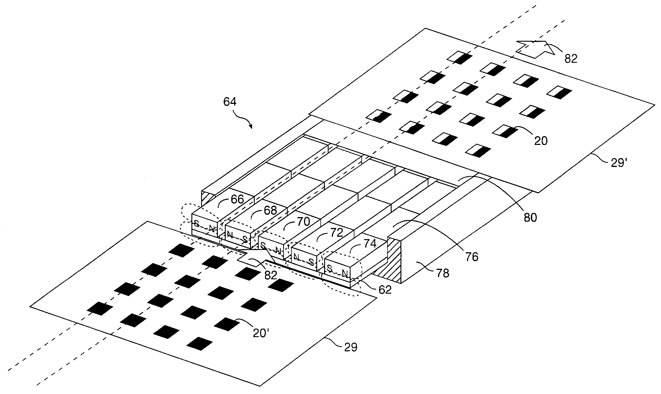
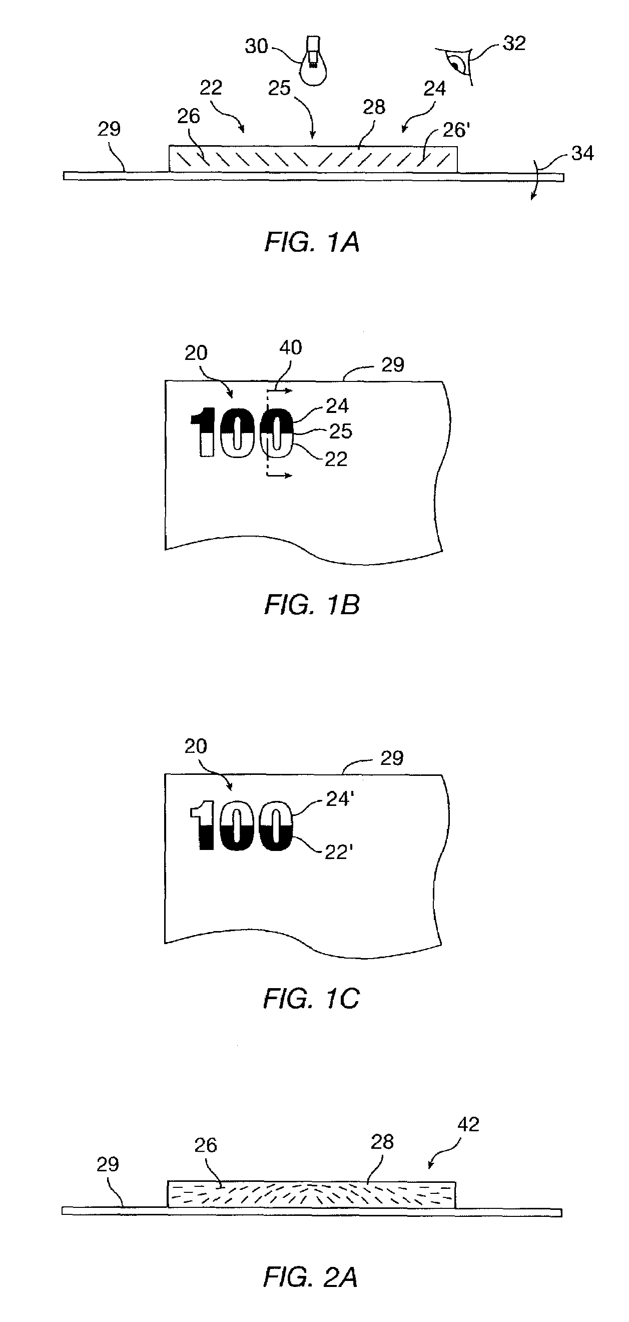
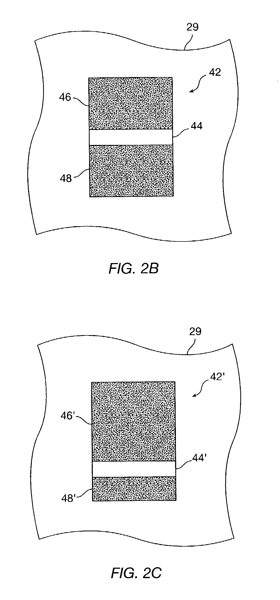
[0053]The present invention in its various embodiments solves the problem of predetermined orientation of magnetic flakes of optically variable ink in a high-speed printing process. Normally, particles of an optically variable pigment dispersed in a liquid paint or ink vehicle generally orient themselves parallel to the surface when printed or painted on to a surface. Orientation parallel to the surface provides high reflectance of incident light from the coated surface. Magnetic flakes can be tilted while in the liquid medium by applying a magnetic field. The flakes generally align in such way that the longest diagonal of a flake follows a magnetic field line. Depending on the position and strength of the magnet, the magnetic field lines can penetrate the substrate at different angles, tilting magnetic flakes to these angles. A tilted flake reflects incident light differently than a flake parallel to the surface of the printed substrate. Reflectance and a hue can bot...


PUM

PropertyMeasurementUnit
angleaaaaaaaaaa
angleaaaaaaaaaa
thickaaaaaaaaaa

Abstract

Apparatus and related methods align magnetic flakes in a carrier, such as an ink vehicle or a paint vehicle to create optically variable images in a high-speed, linear printing operation. Images can provide security features on high-value documents, such as bank notes. Magnetic flakes in the ink are aligned using magnets in a linear printing operation. Selected orientation of the magnetic pigment flakes can achieve a variety of illusive optical effects that are useful for decorative or security applications.

Description

CROSS-REFERENCE TO RELATED APPLICATIONS[0001]This patent application claims priority from U.S. Provisional Patent Application Ser. No. 60 / 410,546 filed Sep. 13, 2002 by Vladimir P. Raksha, from U.S. Provisional Patent Application Ser. No. 60 / 410,547 filed Sep. 13, 2002 by Vladimir P. Raksha, Paul G. Coombs, Charles T. Markantes, Dishuan Chu, and Jay M. Holman, and from U.S. Provisional Patent Application Ser. No. 60 / 396,210 filed Jul. 15, 2002 by Vladimir P. Raksha, Paul G. Coombs, Charles T. Markantes, Dishuan Chu, and Jay M. Holman, the disclosures of which are hereby incorporated in their entirety for all purposes.STATEMENT REGARDING FEDERALLY SPONSORED RESEARCH OR DEVELOPMENT[0002]Not applicable.REFERENCE TO MICROFICHE APPENDIX[0003]Not applicable.BACKGROUND OF THE INVENTION[0004]This invention relates generally to optically variable pigments, films, devices, and images, and more particularly to aligning or orienting magnetic flakes, such as during a painting or printing process...

Claims


Application Information

Patent Timeline
Patent Type & Authority Patents(United States)
IPC IPC(8): B41M1/00B42D15/00B05D3/14B41M1/10B05D5/06B05D5/12B05D7/24B41M1/12B41M3/14B42D15/10
CPCB05D3/207B05D5/06B05D5/061B41F11/02B41M3/00B42D25/29B41M5/00B41M3/14B41P2200/30B42D2033/16B42D2035/20B42D25/369B41M1/00B41F23/00
Inventor RAKSHA, VLADIMIR P.COOMBS, PAUL G.MARKANTES, CHARLES T.CHU, DISHUANHOLMAN, JAY M.
Owner VIAVI SOLUTIONS INC
Learn More