System for coupling roller shade tubes

a technology of roller shade and tube, which is applied in the direction of shutter/movable grille, door/window protection device, curtain suspension device, etc., can solve the problems of inability to achieve the assembly and installation of roller shades in applications that are impossible or impractical to achiev

Active Publication Date: 2006-05-30
LUTRON TECH CO LLC
View PDF12 Cites 66 Cited by
  • Summary
  • Abstract
  • Description
  • Claims
  • Application Information

AI Technical Summary

Benefits of technology

[0015]According to one embodiment of the invention, the coupling assembly includes first and second mounting plates for each support assemblies arranged in a stacked manner. Preferably, the mounting plates include spaced side portions connected by a top portion. The spaced side portions of the first plate are translatably received in spaced notches provided in the inner portion of the associated tube-end fitting. The second mounting plate also includes a bottom portion between the side portions. The second mounting plate also includes a support panel connected to the bottom portion and oriented substantially perpendicular thereto for supporting the associated tube-end fitting.

Problems solved by technology

The space occupied by the fastening elements securing roller tubes of known shade systems creates a gap between the ends of the tubes.
The assembly of the fastening structure for multiple-tube shade systems can be difficult and time-consuming, and may require the use of a specific tool, or tools.
Also, the steps involved in fastening the tubes, and in mounting the multiple-tube roller shade to its supporting structure, may render assembly and installation of the roller shade impractical or impossible in applications where only limited clearance is provided.
The procedures and time required for unfastening the tubes of a known multiple-tube shade system, therefore, tends to deter a user from adjusting shade position by unfastening the tubes.

Method used


Image

  • System for coupling roller shade tubes
  • System for coupling roller shade tubes
  • System for coupling roller shade tubes

Examples


Embodiment Construction

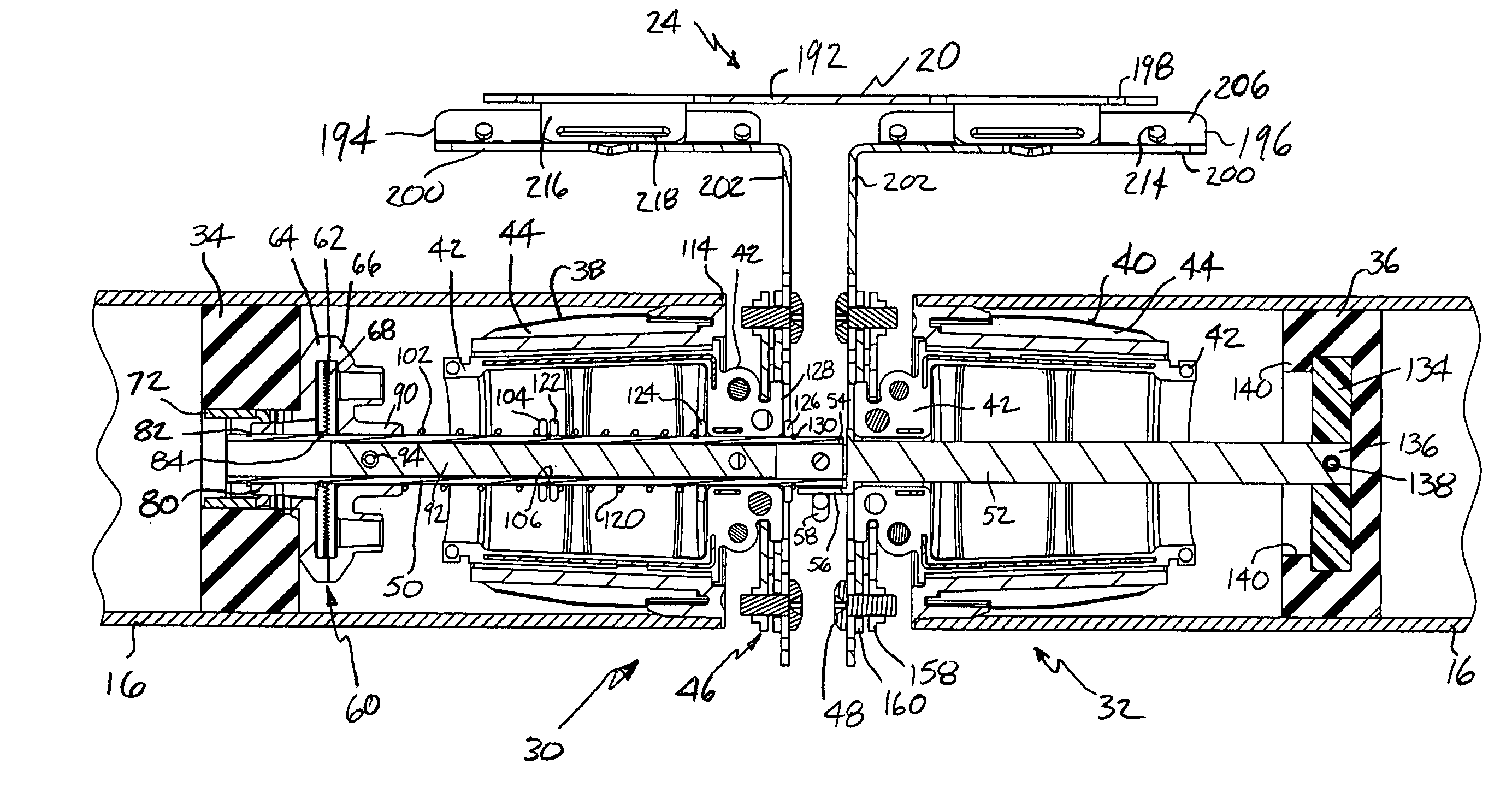
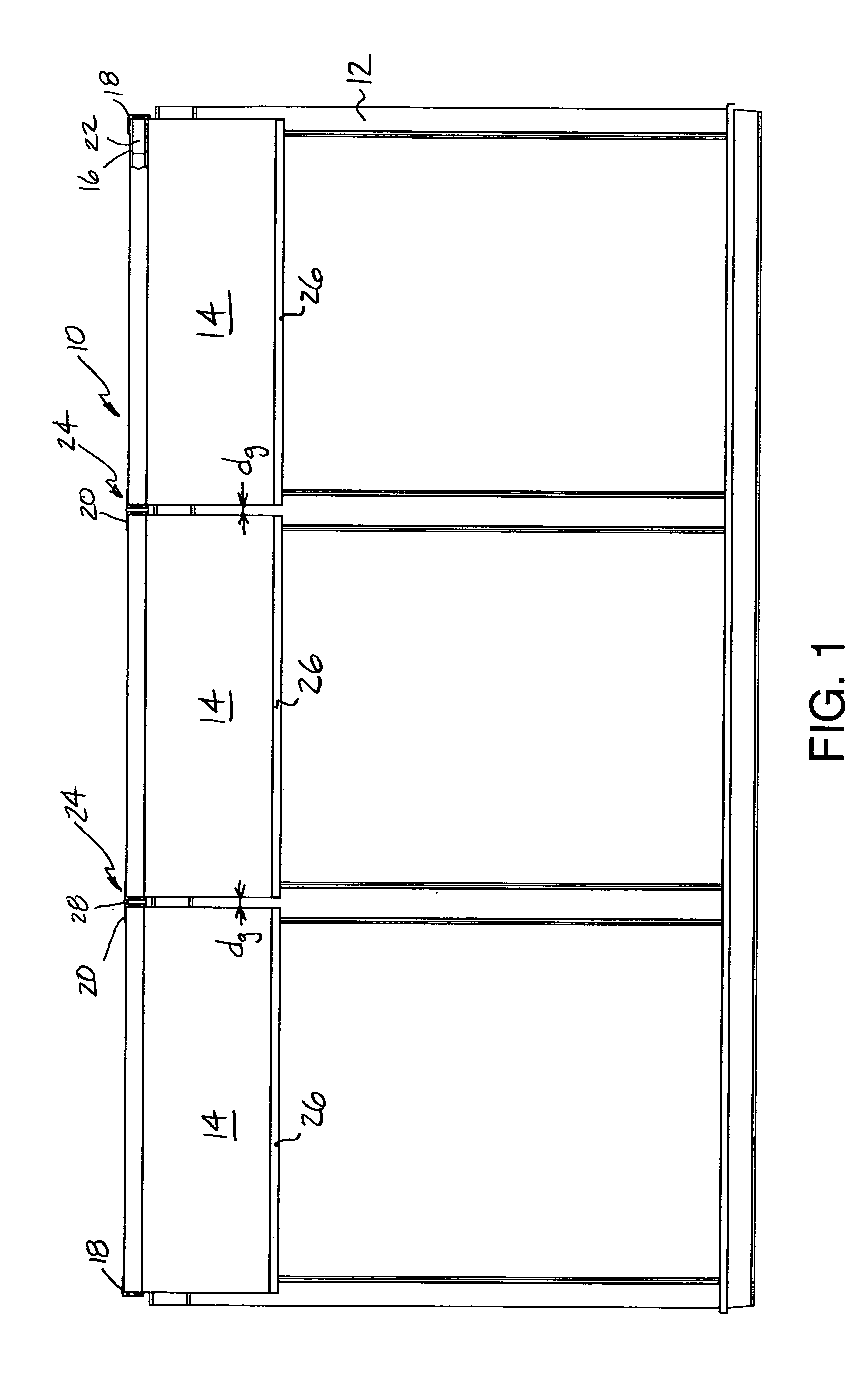
[0034]Referring to the drawings, where like numerals identify like elements, there is illustrated in FIG. 1 a motorized roller shade system 10 according to the present invention. The roller shade system 10 is mounted to the wall of a structure adjacent a window frame 12. The roller shade system 10 includes three shade fabrics 14 separately wound onto three roller tubes 16. The roller tubes 16 are rotatably supported above the window frame 12 by bracket structure 18 located at the opposite ends of the roller shade system 10 and bracket structure 20 located between the roller tubes 16. The roller shade system 10 includes a motor 22 for rotating the roller tubes 16 to wind and unwind the associated shade fabrics 14. The motor 22 of the drive system is shown schematically in FIG. 1 within an end of one of the roller tubes 16 in a known manner adjacent the right-hand end of the roller shade system 10.

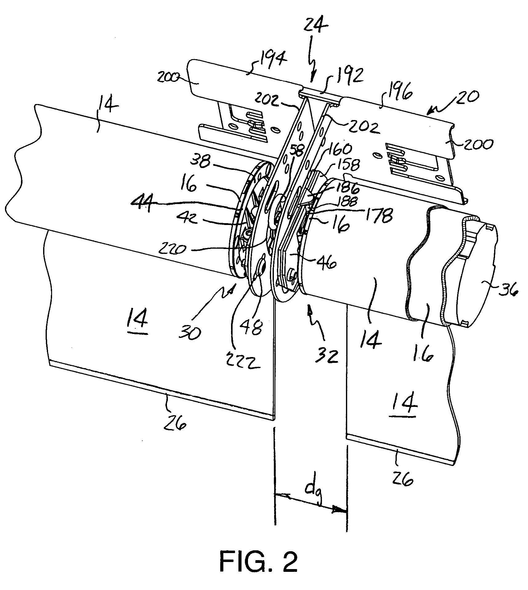
[0035]The present invention provides for rotatable support of adjacently located end por...


PUM


Abstract

A coupling assembly for a multiple-tube roller shade includes a support assembly for rotatably supporting and connecting adjacently located tube-end portions and a clutch mechanism providing relative rotation therebetween. The support assembly includes a tube-end fitting and a torque-transferring drive transfer member contacting the tube. The clutch mechanism includes first and second clutch members respectively engaged and separated in closed and opened positions. A pull bar is translatable within one of the shafts and is moved by a draw pin received in aligned openings of the second clutch member, the shaft and the pull bar. The shaft openings are elongated for movement of the second clutch member between the closed and opened positions. An adjustment member threadedly engages the tube-end fitting for vertical adjustment of the fitting with respect to a support panel. The tube-end fitting is secured to a bracket having elongated openings for horizontal adjustment.

Description

FIELD OF THE INVENTION[0001]The present invention relates generally to motorized roller shades. More particularly, the present invention relates to a system for coupling multiple roller shade tubes together for rotation by the same drive system.BACKGROUND OF THE INVENTION[0002]Motorized roller shade systems include a flexible shade fabric windingly received on a roller tube. The roller tube is supported for rotation about a central axis and is driven by a drive system motor to wind the shade fabric.[0003]Roller shade systems having separate roller tubes secured together for simultaneous rotation are known. The roller tubes are rotatably supported such that the central axes of the tubes are substantially aligned. The tubes of known shade roller systems are fastened together to transfer rotation of one of the tubes, provided by the drive system motor, to the other one of the tubes.[0004]The space occupied by the fastening elements securing roller tubes of known shade systems creates a...

Claims


Application Information

Patent Timeline
Patent Type & Authority Patents(United States)
IPC IPC(8): E06B9/11E04F10/06E06B9/174
CPCE06B9/174E04F10/06E06B2009/1746E06B9/40
Inventor NICHOLS, JR., JOSEPH M.WALKER, MARK A.
Owner LUTRON TECH CO LLC
Why Eureka
Try Eureka