High capacity drawer with mechanical indicator for a dispensing device

a technology of mechanical indicators and drawers, which is applied in the direction of mechanical controls, supporting devices, instruments, etc., can solve the problems of increased risk, control circuitry and wiring, and the need for large amounts of power to keep the compartment locked

Inactive Publication Date: 2006-05-30
OMNICELL
View PDF17 Cites 146 Cited by
  • Summary
  • Abstract
  • Description
  • Claims
  • Application Information

AI Technical Summary

Problems solved by technology

While such systems provide for access controlled dispensing, most require large amounts of power to keep the compartments locked.
Furthermore, systems using lighted indicators require additional power, control circuitry, and wiring.
If an item is caught on the drawer or lid, an increased risk is encountered that the item will become airborne when the drawer or lid is opened.
The airborne item may become lost or may strike a user.

Method used


Image

  • High capacity drawer with mechanical indicator for a dispensing device
  • High capacity drawer with mechanical indicator for a dispensing device
  • High capacity drawer with mechanical indicator for a dispensing device

Examples


Embodiment Construction

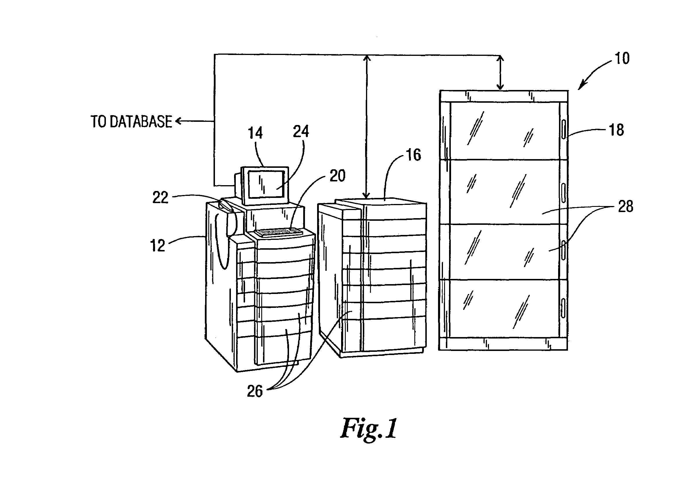
[0043]FIG. 1 is a perspective view of a remote dispensing system 10 located at a decentralized location according to one embodiment of the present invention. The system 10 illustrated in FIG. 1 may be comprised of, for example, an AcuDose-Rx™ cabinet 12 (available from McKesson Automation Inc., 700 Waterfront Drive, Pittsburgh, Pa.) having a control computer 14, and an AcuDose-Rx™ auxiliary cabinet 16. A supply tower 18 is also illustrated. The control computer 14 controls the operation of the cabinet 12, auxiliary cabinet 16, and supply tower 18.

[0044]The control computer 14 may include a memory device (not shown, such as a disk drive, tape drive, CD-ROM drive, etc.) having a local database. The local database may contain inventory, user, and patient information (among others). Alternatively, the control computer 14 may be in communication with another computer (for example, located at the centralized storage location) having a central database which contains the inventory, user, a...


PUM


Abstract

One aspect of the invention relates to an assembly comprising a plurality of bins with a plurality of lids associated therewith. Each of the bins has a lock assembly that includes a catch operable to lock the lid in its closed position and a mechanical indicator responsive to the catch. Another aspect of the invention relates to an automated dispensing cabinet that includes a control computer and a plurality of drawers having a plurality of row assemblies therein. Each row assembly has bins that include a tabbed lid, a lock assembly with a catch operable to engage and disengage the tab, and an indicator responsive to the lock assembly. Methods for dispensing from and restocking the remote dispensing systems are also given, as well as a method for indicating which item is to be dispensed from one of a plurality of bins.

Description

BACKGROUND[0001]1. Field of the Invention[0002]The invention relates generally to an apparatus and method for providing access to items to be dispensed, and relates more particularly to the automatic dispensing of medical supplies. The invention further relates to an apparatus and method for reducing the amount of power consumed by an automatic dispensing system.[0003]2. Description of the Related Art[0004]In typical medical facilities (for example, hospitals, clinics, rest homes, etc), medical supplies are maintained in centralized storage locations and delivered to remote locations (for example, an emergency room, patient ward, etc.) as needed. Once delivered, the medical supplies are then dispensed to a patient. “Medical supply” is intended to include, among others, any item that is administered to or dispensed for a patient or used by a medical caregiver to treat a patient (for example, pharmaceuticals, syringes, sterilized bandages, scalpels, etc.). The invention has been descr...

Claims


Application Information

Patent Timeline
Patent Type & Authority Patents(United States)
IPC IPC(8): E05C7/06A61J7/00E05B47/00E05B47/02E05B65/46E05B65/462G07F11/62
CPCE05B47/0002E05B47/026G07F17/0092G07F11/62E05B65/462E05B47/0004E05B2047/0069
Inventor MEEK, JR., ROBERT B.YOUNG, KIRK A.CONLEY, LOUIS S.SWITALSKI, ERIC J.BOWERS, ALLEN D.
Owner OMNICELL
Why Eureka
Try Eureka