Apparatus operating an isolation switch in coordination with a circuit breaker

a technology of isolation switch and circuit breaker, which is applied in the direction of circuit-breaking switch, contact mechanism, substation, etc., can solve the problem of little room available for operating the isolation switch from the front of the switch gear assembly

Inactive Publication Date: 2006-05-30
BASLER ELECTRIC
View PDF14 Cites 12 Cited by
  • Summary
  • Abstract
  • Description
  • Claims
  • Application Information

AI Technical Summary

Benefits of technology

This patent describes an interlock mechanism used in devices such as locks or switches. It prevents accidental activation when there are no intended movements. The device has two parts: a driving member (like a screw) and a driven member (the part moved back and forth). When the driving member moves, it pushes the driven member along with it. To stop the movement, an interlock member blocks the way. The interlock member has teeth-like structures called edges that keep the driven member from moving backwards and forward. If the movement is straight, the interlock member rotates around a central point where it fits snugly between the driving member and the driven member.

Problems solved by technology

The technical problem of the patent text is to provide a safe and efficient way to isolate and maintain feeder circuits in an electric power distribution system, while also ensuring the coordination of the operation of an isolation switch with a circuit breaker. The limited space available in switch gear assemblies makes it difficult to operate the isolation switch from the front of the switch gear assembly.

Method used


Image

  • Apparatus operating an isolation switch in coordination with a circuit breaker
  • Apparatus operating an isolation switch in coordination with a circuit breaker
  • Apparatus operating an isolation switch in coordination with a circuit breaker

Examples


Embodiment Construction

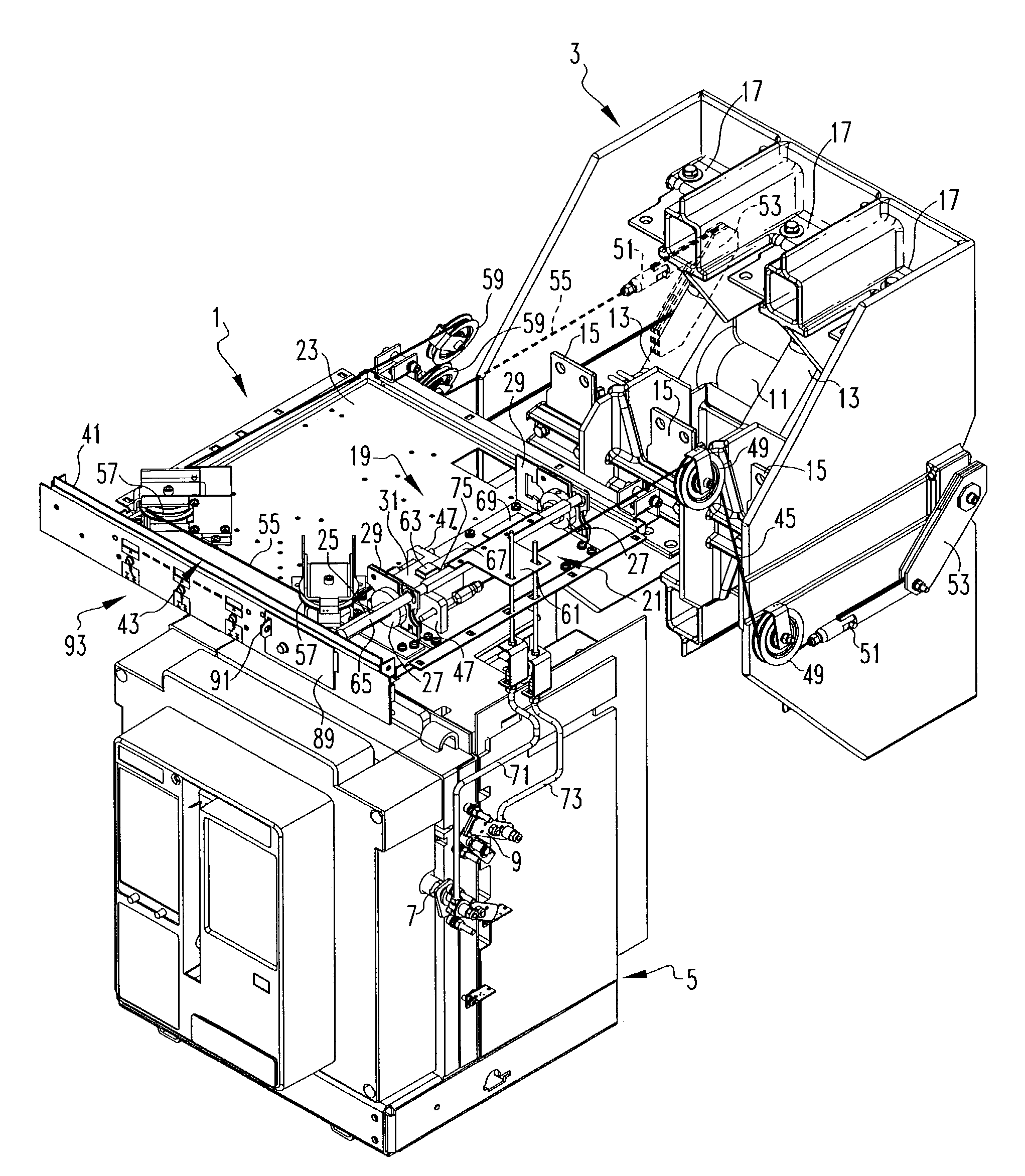
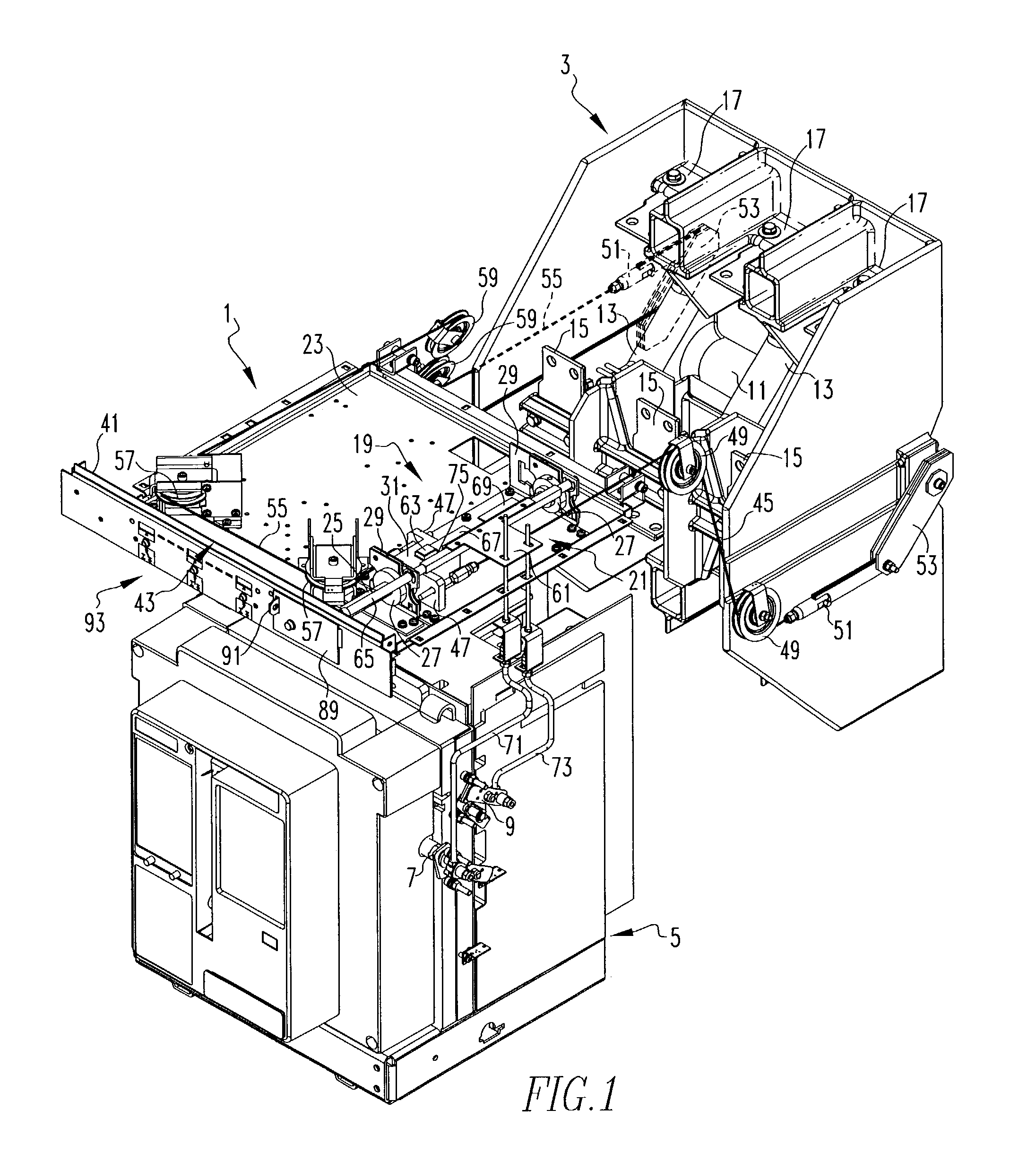
[0019]As shown in FIG. 1, apparatus in the form of a drive / interlock unit 1 operates an isolation switch 3 in coordination with a power circuit breaker 5. As is common, the power circuit breaker 5 has an output 7 which indicates the open and closed position of the circuit breaker contacts. An auxiliary trip bar 9 on the side of the power circuit breaker 5 holds the breaker in the tripped open position when actuated.

[0020]The isolation switch 3 may be of the type described in commonly owned U.S. patent application Ser. No. 10 / 241,122, filed on Sep. 11, 2002. This switch 3 has a shaft 11 carrying a moveable conductor 13 for each phase. A set of terminals 15 is connected by buses (not shown) to corresponding terminals (not shown) on the back of the circuit breaker 5. A second set of terminals 17 is connected to a power source (not shown). An additional set of terminals (not shown) underneath the isolation switch 3 are connected to ground. Rotation of the shaft 11 selectively connects t...


PUM


Abstract

The movable conductors of a three phase isolation switch are incorporated into the electrically insulative molded shaft, thereby mechanically supporting them and isolating them from the metal axle of the shaft. Movable contacts on the ends of each movable conductor are angularly spaced by α degrees, where α is less than 180° and is 90° in the exemplary embodiment. A common fixed load contact is located angularly between, and spaced α degrees from, both the fixed line and ground contacts so that the shaft is rotated only α degrees between a first, closed position, in which the movable conductors connect the fixed load contact for each phase to the corresponding fixed line contact, and a second, grounded position, where the fixed load contact of each phase is connected by the movable conductor to the corresponding fixed ground contact.

Description


Claims


Application Information

Patent Timeline
Owner BASLER ELECTRIC
Why Eureka
Try Eureka