Hearing instrument receiver mounting arrangement for a hearing instrument housing

a technology for hearing instruments and receivers, applied in the field of hearing instruments, can solve the problems of inability to provide consistent feedback performance, inability to guarantee the performance of the hearing instrument, and inability to meet the needs of the user,

Inactive Publication Date: 2006-05-30
SIVANTOS PTE LTD
View PDF16 Cites 12 Cited by
  • Summary
  • Abstract
  • Description
  • Claims
  • Application Information

AI Technical Summary

Benefits of technology

[0006]A hearing instrument for positioning in the ear of a user comprises an electronic assembly which is useful in processing and providing processed sound for output into an ear canal of a hearing instrument user when placed within a housing sized to fit within the ear of the hearing instrument user. The housing includes an internal guide channel and a mounting surface for locating and positioning the electronic assembly.

Problems solved by technology

Existing construction methods and structures for custom hearing instruments do not allow consistent feedback performance and typically require many iterations during manufacture to position an electronic assembly inside a housing of the hearing instrument before a satisfactory performance is achieved, e.g. with respect to feedback.
Such a procedure may take a significant amount of time.
Further, there is no guarantee that the performance will be satisfactory, e.g. possible spikes on a frequency response may still exist because of internal feedback.

Method used


Image

  • Hearing instrument receiver mounting arrangement for a hearing instrument housing
  • Hearing instrument receiver mounting arrangement for a hearing instrument housing
  • Hearing instrument receiver mounting arrangement for a hearing instrument housing

Examples


Embodiment Construction

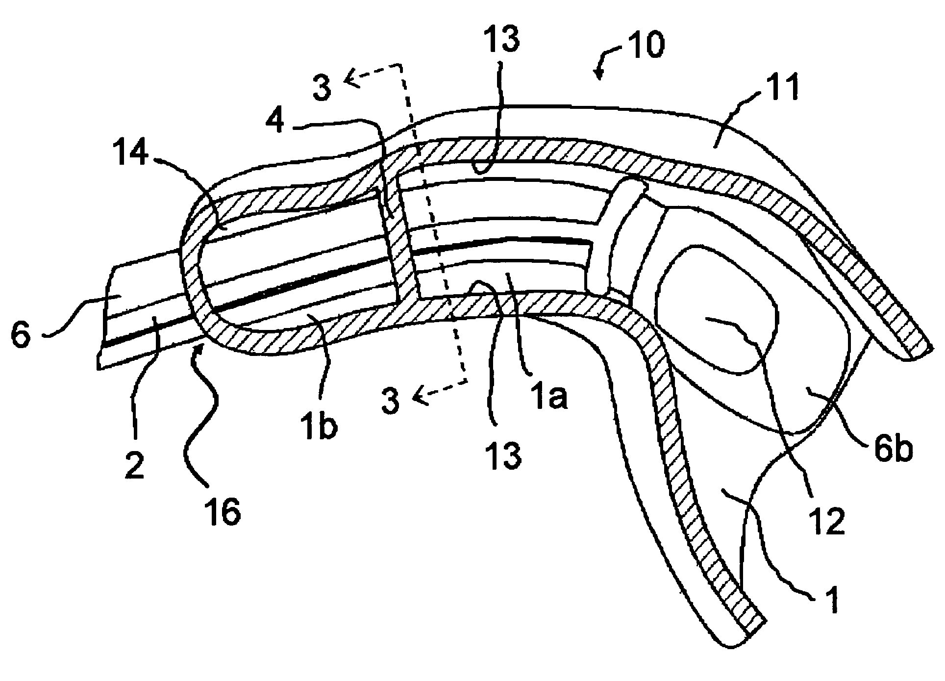
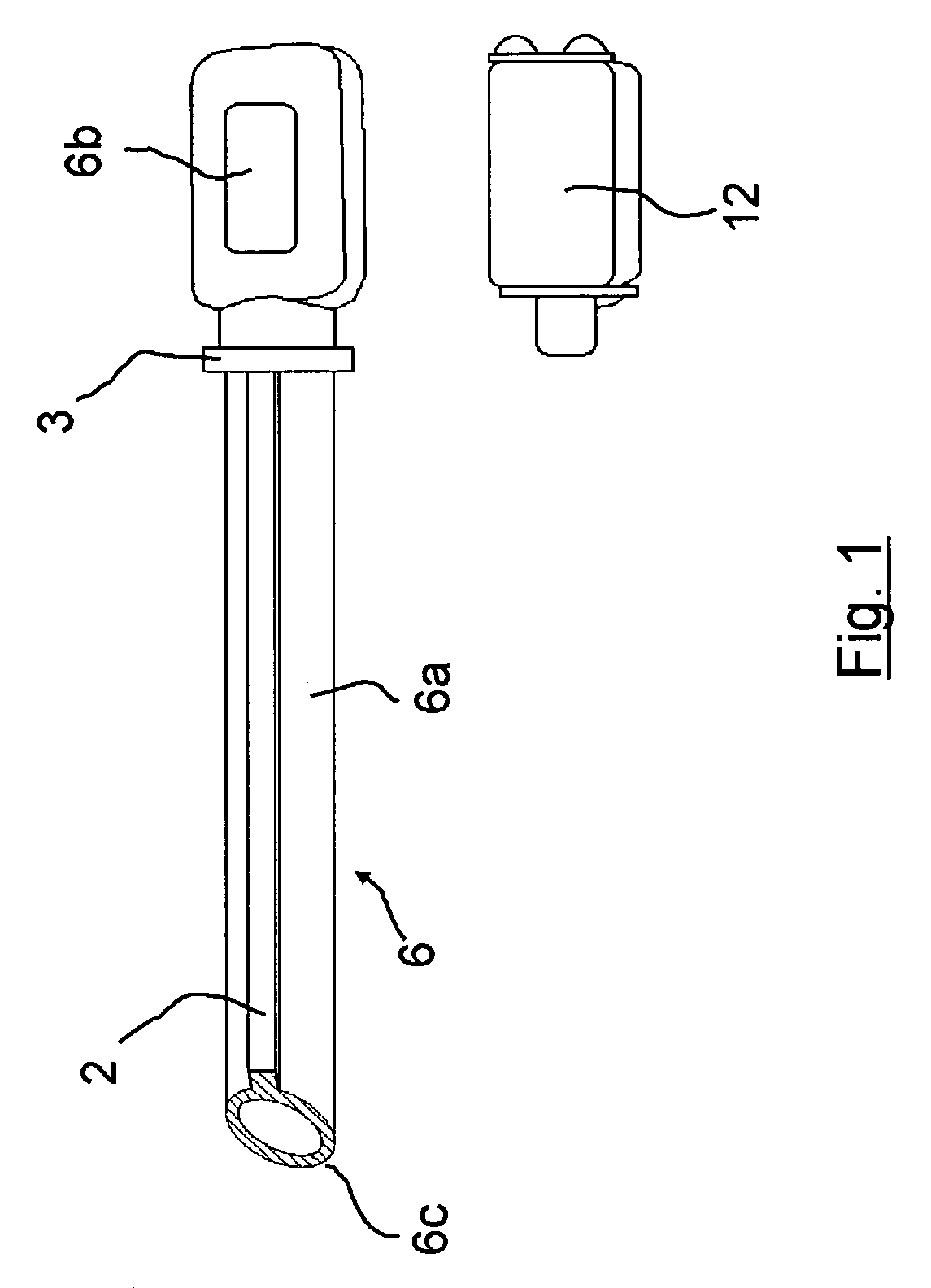
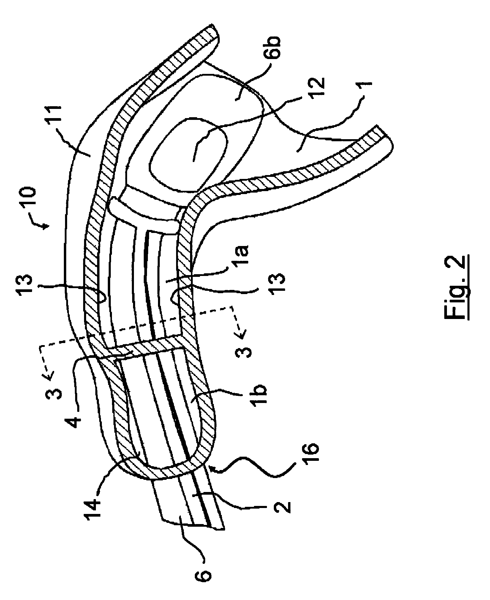
[0015]Referring now to FIG. 1, an electronic assembly tube 6 comprises a substantially tubular pathway 6a and an assembly receptacle 6b. In a currently preferred embodiment, the assembly receptacle 6b is in fluid communication with the tubular pathway 6a. The assembly receptacle 6b is sized to receive the electronic assembly 12.

[0016]Electronic assembly 12 comprises components which process received sound to provide processed sound for output into an ear canal of a hearing instrument user, e.g. a receiver. In a preferred embodiment, electronic assembly 12 is an electromechanical receiver as will be familiar to those of ordinary skill in the hearing instrument arts. In alternative embodiments, electronic assembly 12 may further comprise additional electronic components such as filters; active devices, and the like. The tubular pathway 6a carries the processed sound from the electronic assembly 12 to the outside 16 of the housing 11.

[0017]A barrier stopper 3 is located at a predetermi...


PUM


Abstract

A hearing instrument and method of assembly are disclosed. The hearing instrument comprises an electronic assembly for providing received sound to the ear canal of a hearing instrument user. The electronic assembly is placed within a chamber in a housing sized to fit within the ear of the hearing instrument user. The chamber includes an internal guide channel and mounting surface for locating and positioning the electronic assembly. A volume encompassed within a hearing aid housing may be analyzed, such as with computer software, to identify a location within the chamber to position the electronic assembly, and then the electronic assembly may be incorporated into the housing using a guide channel and mounting surface of the housing for locating and positioning the electronic assembly in the identified location.

Description

[0001]This application claims priority to U.S. Provisional Application Ser. No. 60 / 365,930 filed Mar. 20, 2002, entitled “Hearing Aid Instrument and Related Production Process.”FIELD OF THE INVENTION[0002]The present invention relates to the field of hearing instruments.BACKGROUND OF THE INVENTION[0003]Hearings instruments may be inserted either partially or completely into a user's ear canal. Typically, hearing instruments, especially custom hearing instruments, must be constructed to minimize feedback when deployed in the user's ear canal.[0004]Existing construction methods and structures for custom hearing instruments do not allow consistent feedback performance and typically require many iterations during manufacture to position an electronic assembly inside a housing of the hearing instrument before a satisfactory performance is achieved, e.g. with respect to feedback.[0005]Often, a closing procedure is done by a trial and error method with an assembly worker moving the electro...

Claims


Application Information

Patent Timeline
Patent Type & Authority Patents(United States)
IPC IPC(8): H04R25/00
CPCH04R25/456H04R25/658H04R25/604
Inventor SALTYKOV, OLEG
Owner SIVANTOS PTE LTD
Why Eureka
Try Eureka