Frictional clutch assembly

a clutch and friction technology, applied in the direction of mechanical actuator clutches, mechanical equipment, gearing, etc., can solve the problem of reducing the cost of machines

Inactive Publication Date: 2006-06-06
LIU HO TUNG
View PDF4 Cites 2 Cited by
  • Summary
  • Abstract
  • Description
  • Claims
  • Application Information

AI Technical Summary

Benefits of technology

[0009]The main objective of the invention is to provide a clutch assembly that can transmit power in a unidirectional manner. The clutch assembly has a driving assembly and a transmission assembly. The driving assembly has an input axle and at least one driving gear mounted on and driven by the input axle. The transmission assembly is connected to the driving assembly and has an output axle, at least one driven gear, an inner axle and a unidirectional transmitting device. The output axle has an axis and a central hole axially defined through the output axle. The at least one driven gear is rotatably mounted on the output axle and engages with the at least one driving gear. The inner axle is slidably mounted in the central hole in the output axle and is engaged with the output axle to rotate with the output axle. The unidirectional transmitting device is mounted in the output axle between the at least one driven gear and the inner axle to make the inner axle be driven by the at least one driven gear to rotate in a unidirectional manner and to provide a clutching effect when the inner axle slides relative to the output axle.

Problems solved by technology

However, the conventional unidirectional transmitting assembly (10) does not have a function of a clutch, so it is necessary to add an additional clutch device for a machine with a conventional unidirectional transmitting assembly and this renders the machine expensive.

Method used


Image

  • Frictional clutch assembly
  • Frictional clutch assembly
  • Frictional clutch assembly

Examples


first embodiment

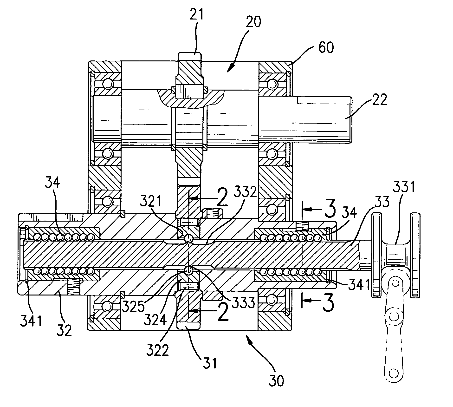
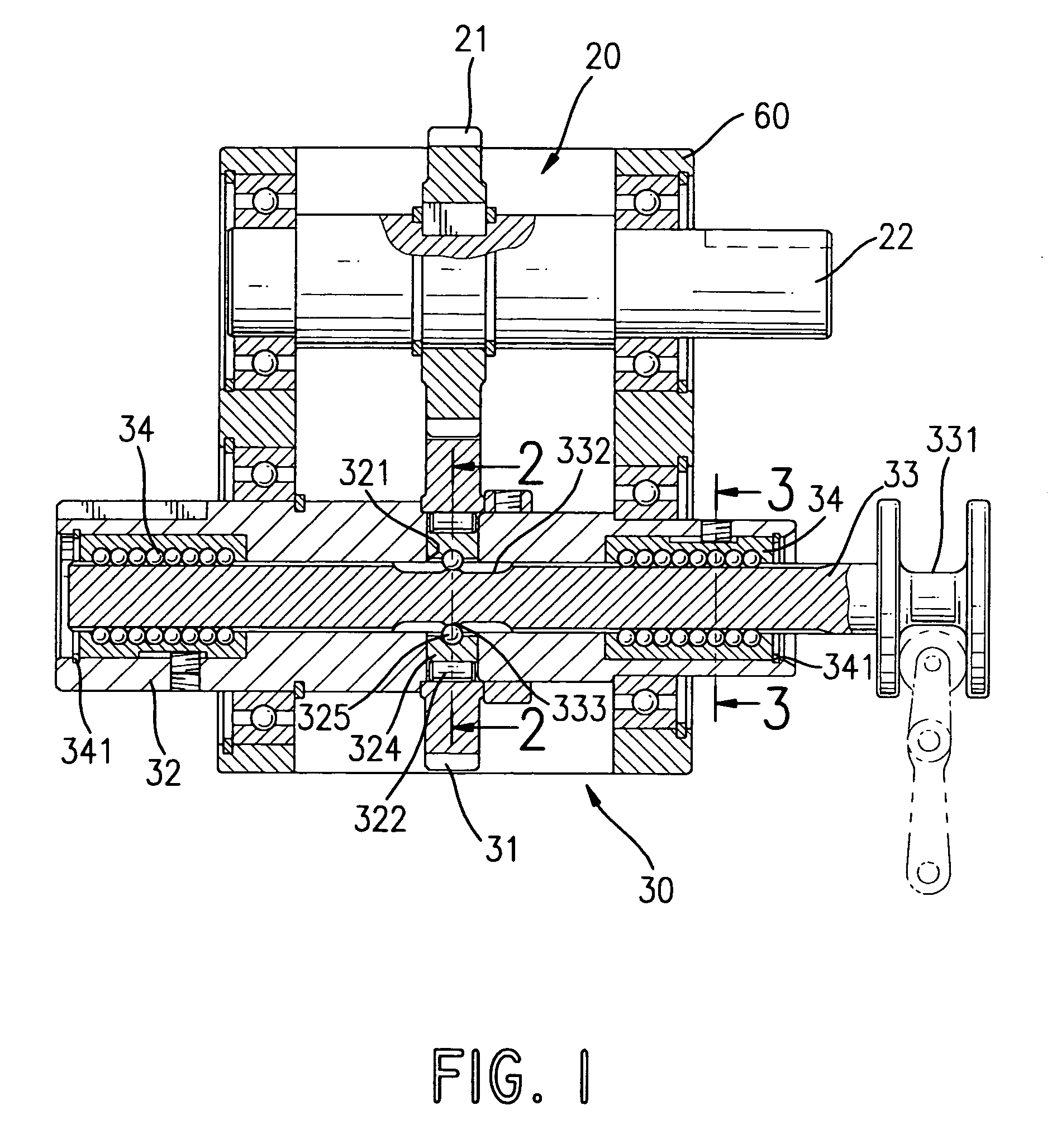
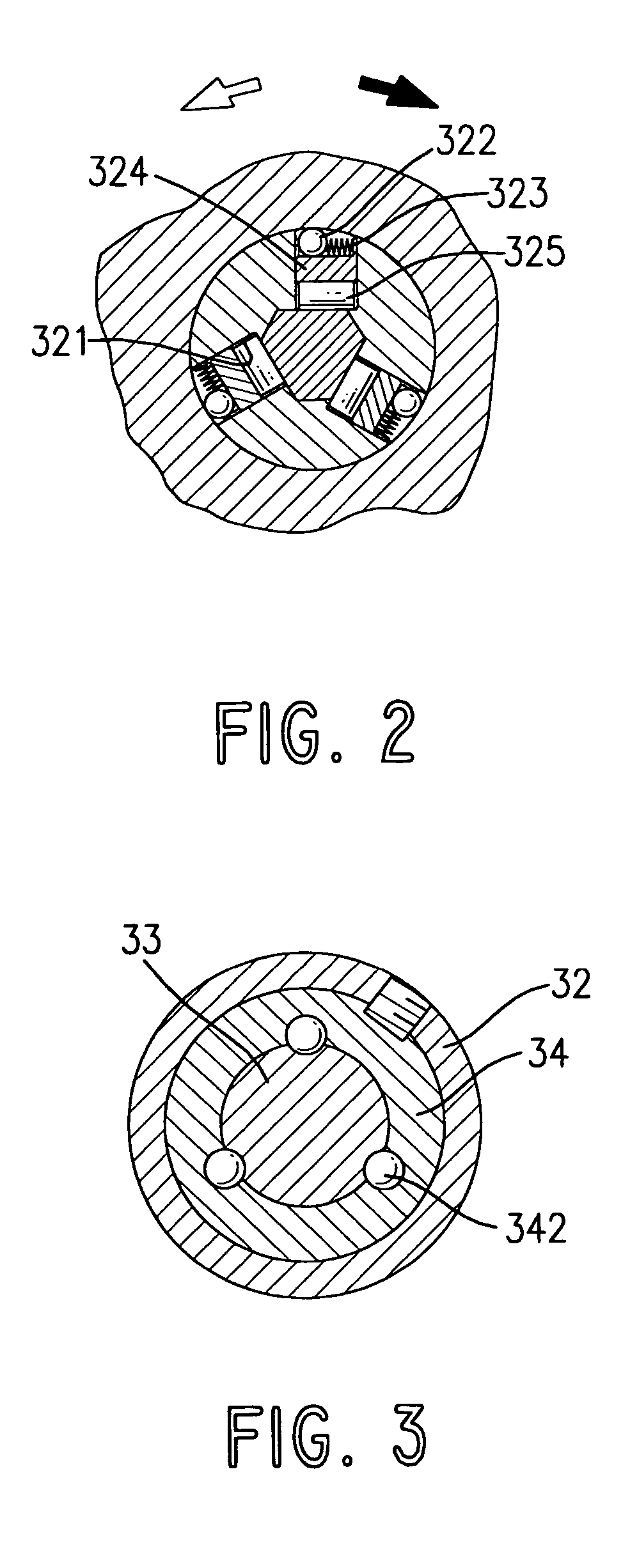
[0017]With reference to FIGS. 1 to 4, a clutch assembly in accordance with the present invention comprises a driving assembly (20) and a transmission assembly (30). The driving assembly (20) comprises an input axle (22) and a driving gear (21). The driving assembly (20) is adapted to be mounted in a housing (60) of a machine in which the clutch assembly is mounted. The input axle (22) is rotatably mounted on the housing (60) and is connected and driven by a driving device, such as a motor. The driving gear (21) is mounted on and driven by the input axle (22) to rotate with the input axle (22).

[0018]The transmission assembly (30) is connected to the driving assembly (20) and is adapted to be mounted in the housing (60). The transmission assembly (30) comprises a driven gear (31), an output axle (32), an inner axle (33) and a unidirectional transmitting device. The output axle (32) is rotatably mounted in the housing (60) and has an axis and a central hole axially defined through the ...

second embodiment

[0025]With reference to FIG. 5, a clutch assembly comprises a driving assembly (40) and a transmission assembly (50). The driving assembly (40) comprises an input axle (42) and multiple driving gears (41). The driving gears (41) are mounted on and driven by the input axle (42) to rotate with the input axle (42).

[0026]The transmission assembly (50) comprises multiple driven gears (51), an output axle (52), an inner axle (53) and a unidirectional transmitting device. The structures of the output axle (52) and the inner axle (53) are the same as those of the first embodiment aforementioned and are not further described. The driven gears (51) are rotatably mounted on the output axle (52) and engage respectively with the driving gears (41).

[0027]The unidirectional transmitting device is mounted in the output axle (52) and between the driven gears (51) and the inner axle (53) to make the inner axle (53) being driven by one of the driven gears (51) rotate in a unidirectional manner. The un...


PUM


Abstract

A clutch assembly has a driving assembly and a transmission assembly. The driving assembly has an input axle and at least one driving gear. The transmission assembly is connected to the driving assembly and has an output axle, at least one driven gear, an inner axle and a unidirectional transmitting device. The driven gear is rotatably mounted on the output axle and engages with the driving gear. The inner axle is slidably mounted in the output axle and is engaged with the output axle to rotate with the output axle. The unidirectional transmitting device is mounted in the output to make the inner axle being driven by the at least one driven gear rotate in a unidirectional manner and to provide a clutching effect when the inner axle slides relative to the output axle.

Description

BACKGROUND OF THE INVENTION[0001]1. Field of the Invention[0002]The present invention relates to a clutch assembly, and more particularly to a frictional clutch assembly that can transmit power in a unidirectional manner.[0003]2. Description of Related Art[0004]With reference to FIG. 6, a conventional unidirectional transmitting assembly (10) in accordance with the prior art comprises a driving axle (11), a transmitting sleeve (13), multiple rollers (12) and an output axle (14). The transmitting sleeve (13) is received in the driving axle (11) and has multiple cutouts (15) defined in the outer surface of the sleeve (13). Each cutout (15) has a wide segment and a narrow segment and receives one of the rollers (12). The output axle (14) is mounted in and engages with the transmitting sleeve (13) to rotate with the transmitting sleeve (13).[0005]When the driving axle (11) rotates along a direction corresponding to the narrow segments of the cutouts (15), clockwise as shown by the black...

Claims


Application Information

Patent Timeline
Patent Type & Authority Patents(United States)
IPC IPC(8): F16H3/08F16D21/04F16D41/08F16H3/083
CPCF16D21/04F16D41/088F16H3/083Y10T74/19219Y10T74/19465Y10T74/19447
Inventor LIU, HO-TUNG
Owner LIU HO TUNG
Why Eureka
Try Eureka