Setting tool

a technology of setting tool and stop member, which is applied in the field of setting tool, can solve the problems of affecting the service life of both the stop member and the setting piston, affecting the service life of the stop member, and affecting the operation of the setting tool

Active Publication Date: 2006-06-06
HILTI AG
View PDF10 Cites 16 Cited by
  • Summary
  • Abstract
  • Description
  • Claims
  • Application Information

AI Technical Summary

Benefits of technology

[0008]This and other objects of the present invention, which will become apparent hereinafter are achieved by providing at least one of the conical active surface of the setting tool and the conical active surface of the stop member with a friction-reducing coating. This prevents jamming of the setting piston in the stop ring. Thereby, the service life of both the stop member and the setting piston is noticeably increased.
[0009]According to an advantageous embodiment of the present invention, the coating is essentially non-compressible. Thereby, the service life of the coating is increased, and it is capable to prevent jamming.
[0010]Preferably, the coating has a sliding friction coefficient equal to or less than 0.10. With such a coefficient, a noticeable reduction of friction between the conical active surface of the stop member and the setting piston is achieved.
[0011]Advantageously, the coating has a thickness of from 1 to 20000 nm, which insures a cost-effective manufacturing of the stop member and the setting piston and an increase of their service life.

Problems solved by technology

The drawback of the structure of the above-discussed U.S. patent consists in that under certain operational conditions, the setting piston with its conical surface can be jammed in the conical leadthrough of the first rigid ring.
Such jamming often leads to breakdown of the setting tool parts and to interruptions of the operation of the setting tool as after a while, release of jamming is not possible.

Method used


Image

  • Setting tool
  • Setting tool

Examples


Embodiment Construction

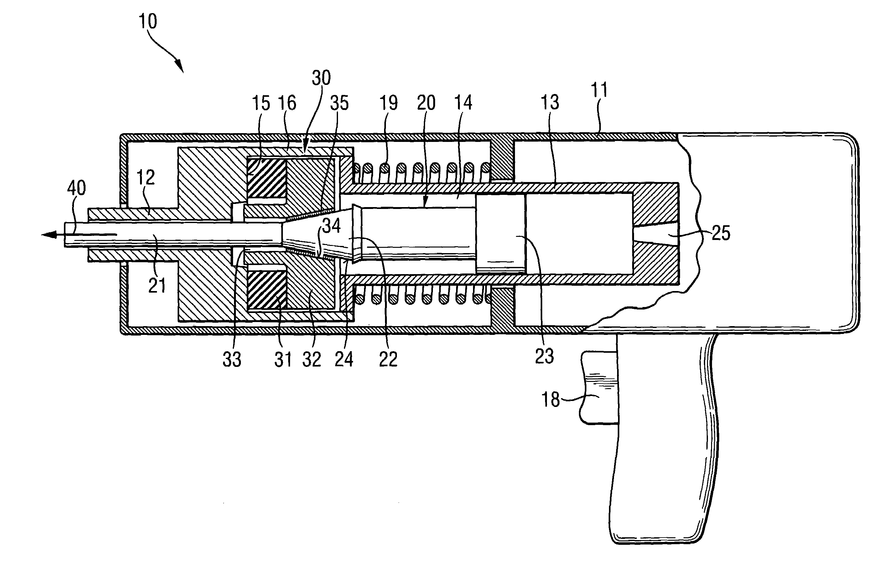
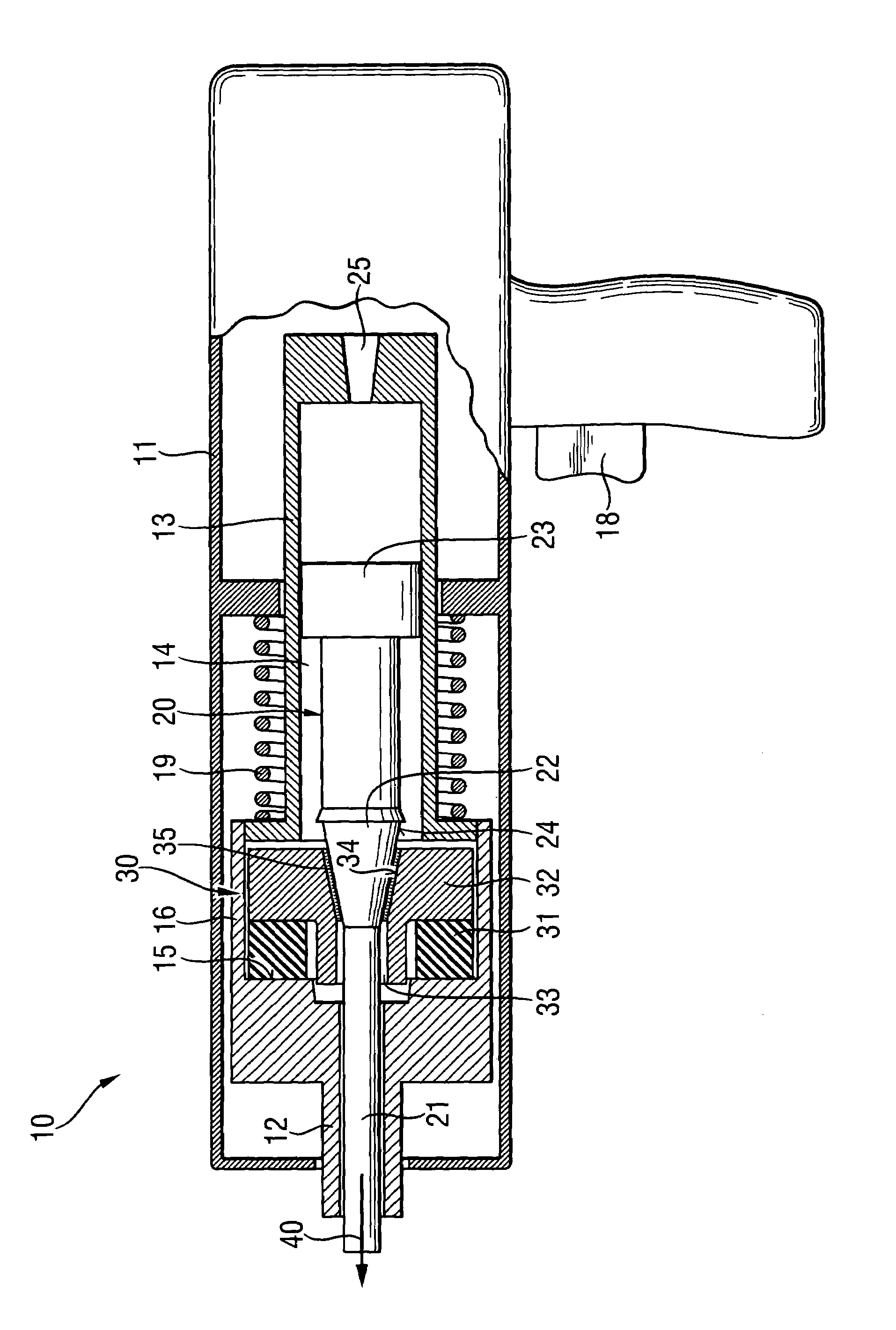
[0016]A setting tool 10 according to the present invention, which is shown in the drawing, has a one-or multi-part housing 11, a piston guide 13 arranged in the housing 11, and a setting piston 20 displaceably arranged in hollow chamber 14 of the piston guide 13. The setting piston 20 is driven by a propellant or by products of its reaction, e.g., by combustion gases, etc.

[0017]The setting piston 20 has a piston stem 21 and a piston head 23 provided at the rear, in the setting direction 40, end of the stem 21. Spaced from the piston head 23, there is provided, on the stem 21, a band 22. The band 22 is adjoined by a active surface 24 extending in the direction of the piston stop device 30. Alternatively to the arrangement shown in the drawings, the band 22 can be arranged in the setting direction region of the piston head 23. The piston guide 13 is displaceably arranged in the sleeve-shaped housing 11 and is supported against a spring 19. At the end of the piston guide 13 facing in t...


PUM


Abstract

A setting tool for driving fastening elements includes a piston device (30) for the setting piston (20) and arranged in a setting direction end region of the hollow chamber (14) of the piston guide (13), with the piston stop device (30) having a stop member (32) adjoining the hollow chamber (14) in the setting direction and including a leadthrough (33) having an inner conical active surface (34) that cooperates with the conical active surface (24) of the setting piston (20), and with at least one of the active conical surface (24) and the active conical surface (34) being provided with a friction-reducing coating (35).

Description

BACKGROUND OF THE INVENTION[0001]1. Field of the Invention[0002]The present invention relates to a setting tool for driving in fastening elements and including a piston guide having a hollow chamber, a setting piston axially displaceably arranged in the hollow chamber of the piston guide and having a piston head, a piston stem, and a conical active surface, and a piston stop device for the setting piston and arranged in a setting direction end region of the hollow chamber, with the piston stop device having a stop member adjoining the hollow chamber in the setting direction and having a conical active surface that cooperates with the conical active surface of the setting piston.[0003]2. Description of the Prior Art[0004]Setting tools of the above-described type are driven with solid, gaseous, or fluid fuels or with compressed air. In combustion-driven setting tools, the setting piston is driven by combustion gases. With these setting tools, fastening elements, such as, e.g., nails o...

Claims


Application Information

Patent Timeline
Patent Type & Authority Patents(United States)
IPC IPC(8): B25C1/14
CPCB25C1/14
Inventor ROHRMOSER, GUENTERJAKOB, ROBERTBOENIG, STEFAN
Owner HILTI AG
Why Eureka
Try Eureka