Expansion ring for mass transfer column and method employing same

Active Publication Date: 2006-06-06
KOCH GLITSCH INC
View PDF10 Cites 7 Cited by
  • Summary
  • Abstract
  • Description
  • Claims
  • Application Information

AI Technical Summary

Benefits of technology

[0009]In one aspect, the present invention is directed to an expansion ring for use in a mass transfer column having an external shell that defines an open internal region within the column. The expansion ring underlies and supports a vapor-liquid contact tray disposed within the internal region of the column. The expansion ring comprises a vertical leg and a tray support flange that extends radially inwardly from an upper edge of the vertical leg. The expansion ring has a first end segment and a second end segment defining an opening or cutout in both the vertical leg and tray support flange portions of the expansi

Problems solved by technology

Considerable time and effort, however, is normally required to remove the existing support rings and weld new support rings at the desired location on the column shell.
In addition, the process of cutting out the old support rings and welding new support rings may be hazardous if combustible fluids or residues are still present in the column or if the structural integrity of the column shell is weakened or otherwise negatively affected by the cutting and welding.
This post-revamp stress relieving and pressure testing of the column further adds to the costs and delays associated with replacing the support rings in revamped columns.
One problem resulting from the use of t

Method used


Image

  • Expansion ring for mass transfer column and method employing same
  • Expansion ring for mass transfer column and method employing same
  • Expansion ring for mass transfer column and method employing same

Examples


Embodiment Construction

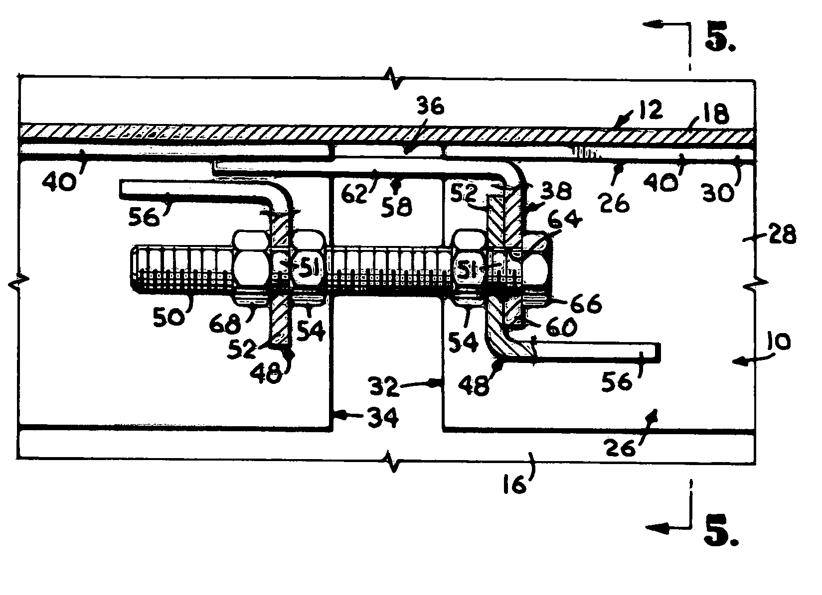
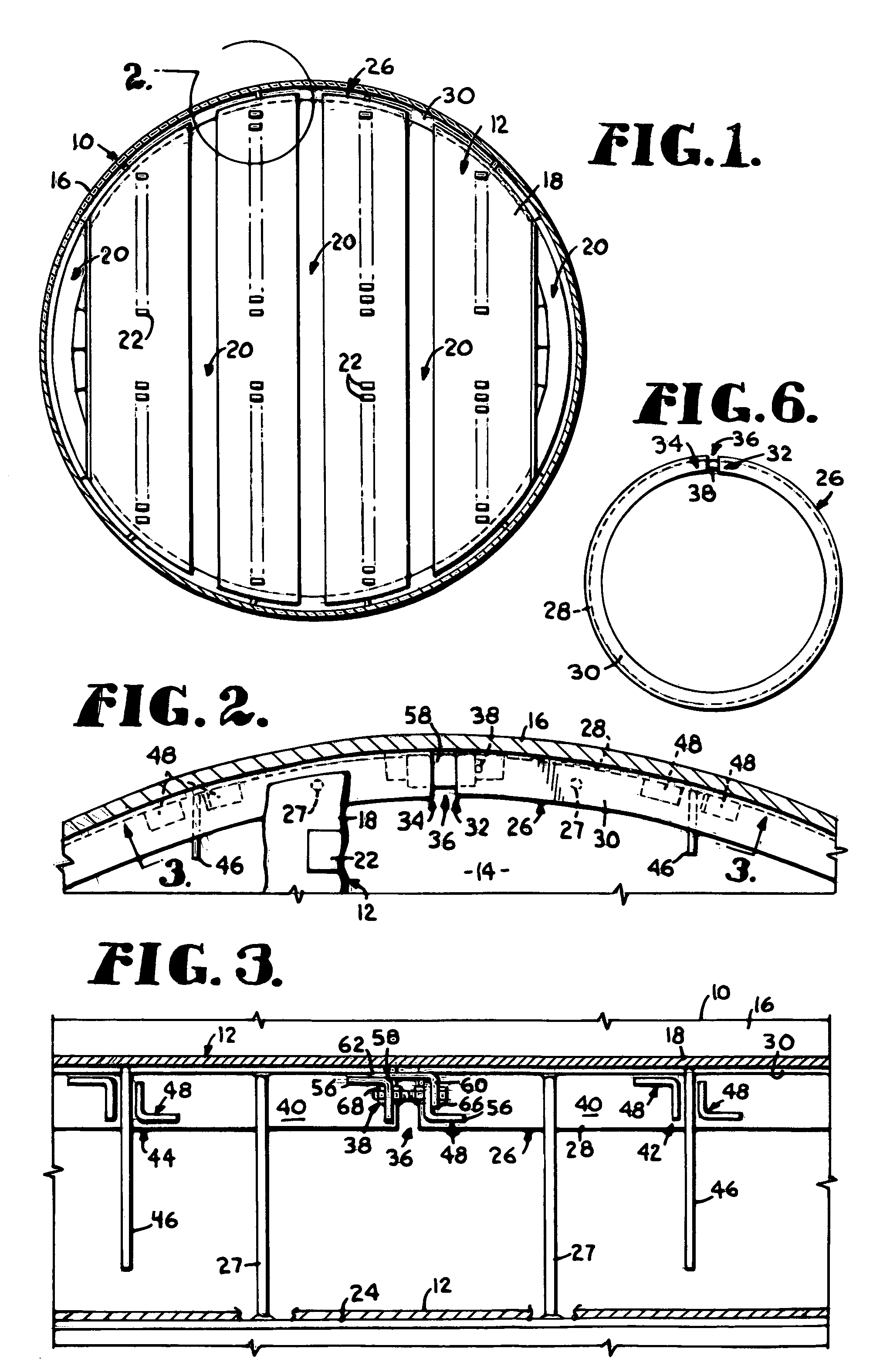
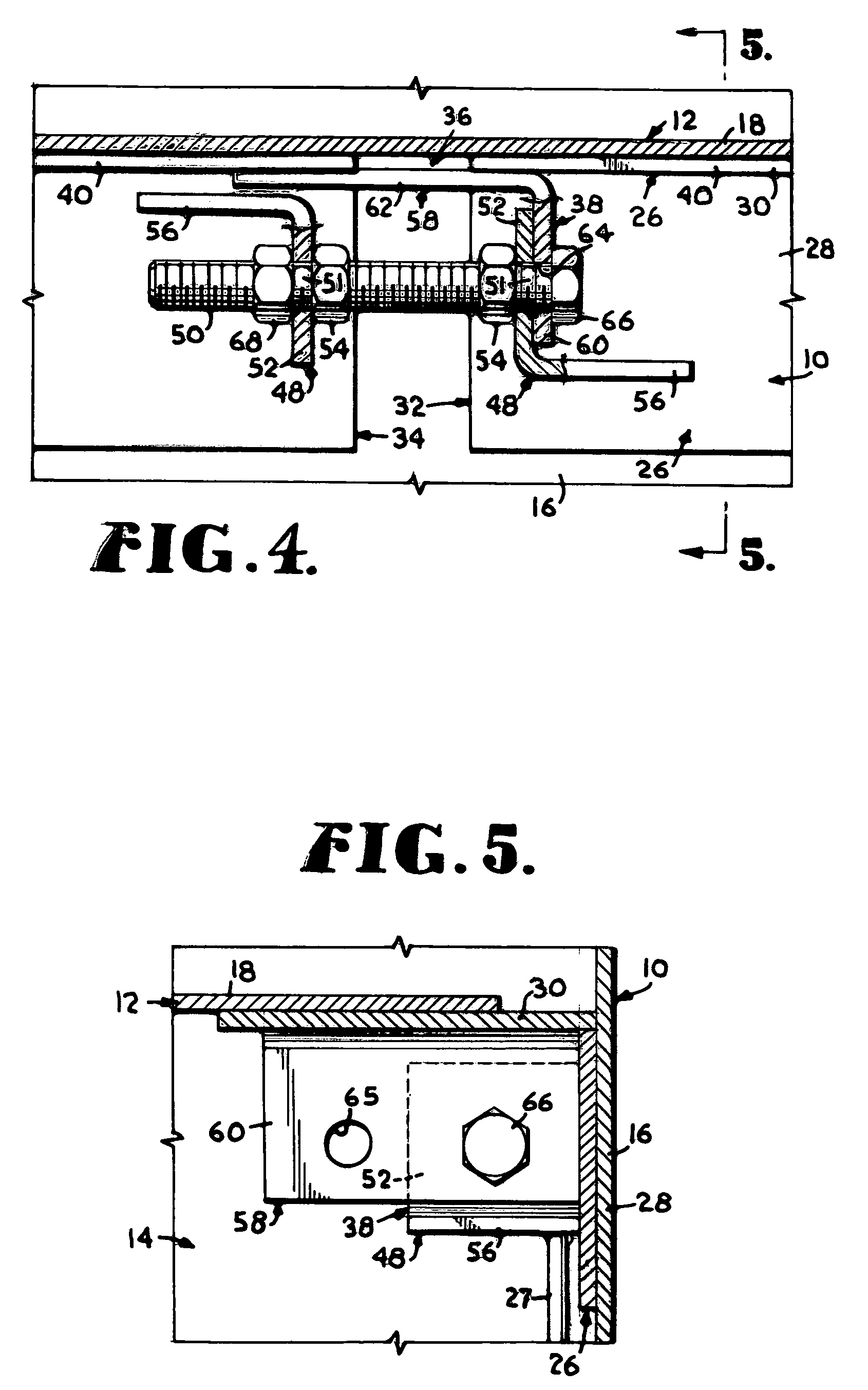
[0019]Turning now to the drawings in greater detail and initially to FIGS. 1 and 2, a mass transfer column is represented broadly by the numeral 10 and includes a plurality of vapor-liquid contact trays 12 supported in vertically spaced apart relation within an open internal region 14 defined by an external cylindrical shell 16. Column 10 is of the type in which mass transfer and / or heat exchange occurs between fluid streams flowing within the internal region 14 of the column 10. A common use of such columns is to effect mass transfer between one or more downwardly flowing liquid streams and one or more ascending vapor streams. Alternatively, the fluid streams can both be liquid streams or a gas stream and a liquid stream. The trays 12 are used to facilitate contact between the fluid streams as they flow within the column 10.

[0020]The fluid streams are directed to the column 10 through any suitable number of feed lines (not shown) positioned at appropriate locations along the height...


PUM

PropertyMeasurementUnit
Circumferenceaaaaaaaaaa

Abstract

A mass transfer column (10) is provided with at least one vapor-liquid contact tray (12) that is disposed within the open internal region (14) defined by a shell (16) of the column (10). At least one expansion ring (26) underlies and supports the vapor-liquid contact tray (12). An expander (38) is associated with first and second end segments (32, 34) of the expansion ring (26) that define a cutout (36) in the expansion ring (26). The expander (38) includes brackets (48) welded to the end segments (32, 34) and a threaded member (50) that extends through the brackets (48) and carries nuts (54). Turning the nuts (54) against facing surfaces of the brackets (48) causes the first and second end segments (32, 34) of the expansion ring (26) to be forced apart to cause an increase in the circumference of the expansion ring (26), thereby sealing the expansion ring (26) against the inner surface of the column shell. At least one seal plate (58) is positioned on the threaded member (50) to block the cutout (36) in the expansion ring (26) Rods (27) extend between the expansion ring (26) and a support ring (24) that is welded to the column shell (16) to transfer a portion of the load carried by the expansion ring (26) to the support ring (24).

Description

CROSS-REFERENCE TO RELATED APPLICATION[0001]This application claims the benefit of provisional application Ser. No. 60 / 464,467, filed Apr. 22, 2003.BACKGROUND OF THE INVENTION[0002]This invention relates generally to mass transfer columns and, more particularly, to an apparatus and method for supporting and sealing trays within such columns.[0003]Mass transfer columns, including heat exchange columns, typically include an upright shell and a plurality of horizontally disposed trays that are positioned within the shell and are used to facilitate mass or heat transfer between fluid streams flowing within the column. The fluid streams are normally one or more downwardly flowing liquid streams and one or more ascending vapor streams, although other combinations of fluid streams are possible. Each tray includes a plurality of vapor passages that allow the vapor stream to ascend through the tray for interaction with the liquid stream flowing across an upper surface of the tray. A pluralit...

Claims


Application Information

Patent Timeline
IPC IPC(8): B01F3/04B01D3/32
CPCB01D3/328B01D3/324B01D3/32B01D3/00B01F23/20
Inventor GAGE, GARY W.
Owner KOCH GLITSCH INC
Why Eureka
Try Eureka