Developing unit for image forming apparatus

a technology of image forming apparatus and development unit, which is applied in the direction of electrographic process apparatus, instruments, optics, etc., can solve the problems of image quality rapidly deterioration, and achieve the effect of preventing toner stress and preventing toner leakag

Inactive Publication Date: 2006-06-06
S PRINTING SOLUTION CO LTD
View PDF7 Cites 9 Cited by
  • Summary
  • Abstract
  • Description
  • Claims
  • Application Information

AI Technical Summary

Benefits of technology

[0011]An aspect of the present invention is to provide a developer for an image forming apparatus which uniformly regulates the quantity of toner which is transferred from one toner chamber to another toner chamber during development, prevents the toner from leaking out, and prevents toner stress from occurring due to the excessive toner transfer to one toner chamber.

Problems solved by technology

In addition, the toner stress increases so that the image quality rapidly deteriorates.

Method used


Image

  • Developing unit for image forming apparatus
  • Developing unit for image forming apparatus
  • Developing unit for image forming apparatus

Examples


Embodiment Construction

[0025]Reference will now be made in detail to the embodiments of the present invention, examples of which are illustrated in the accompanying drawings, wherein like reference numerals refer to the like elements throughout. The embodiments are described below to explain the present invention by referring to the figures.

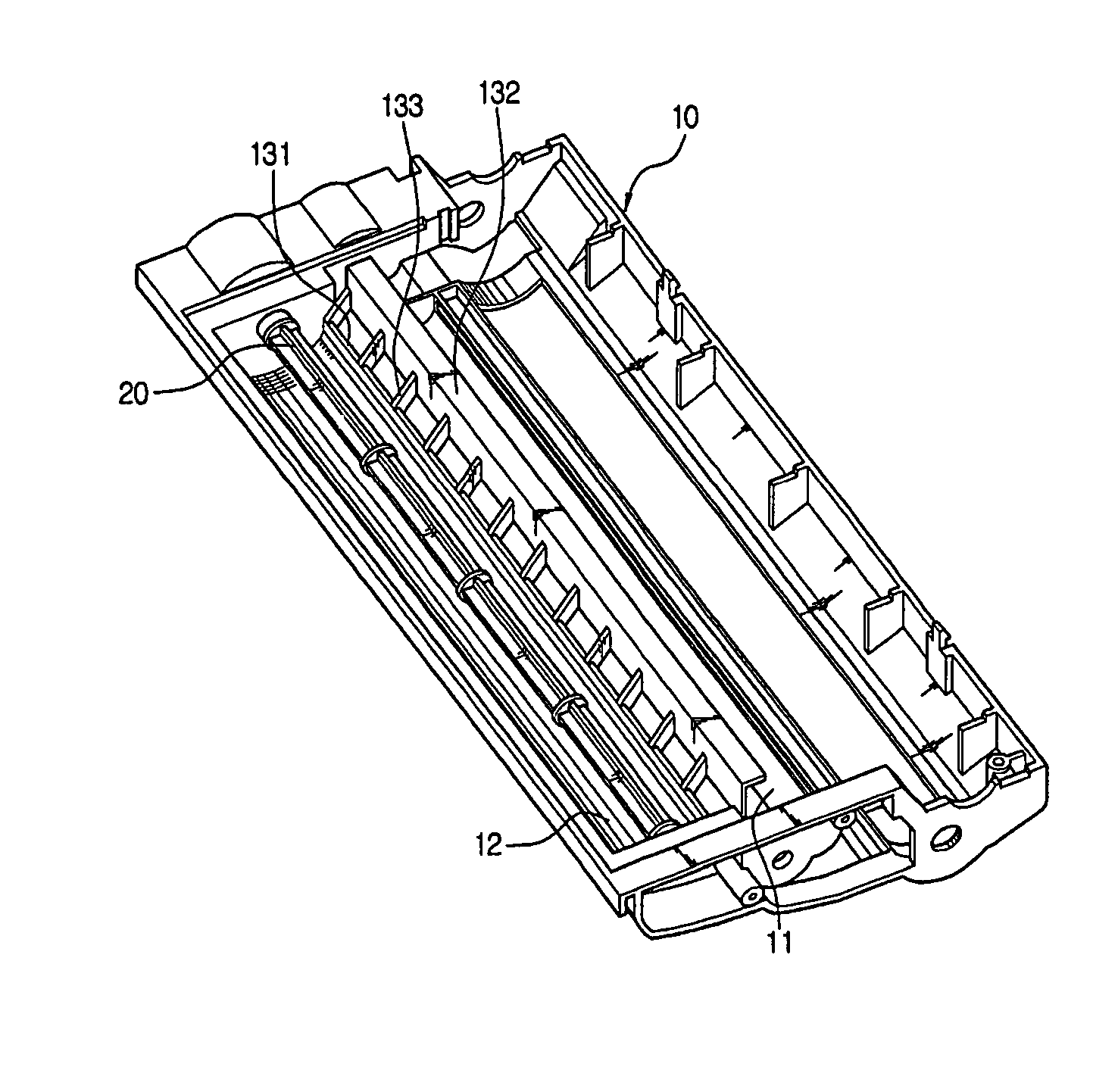
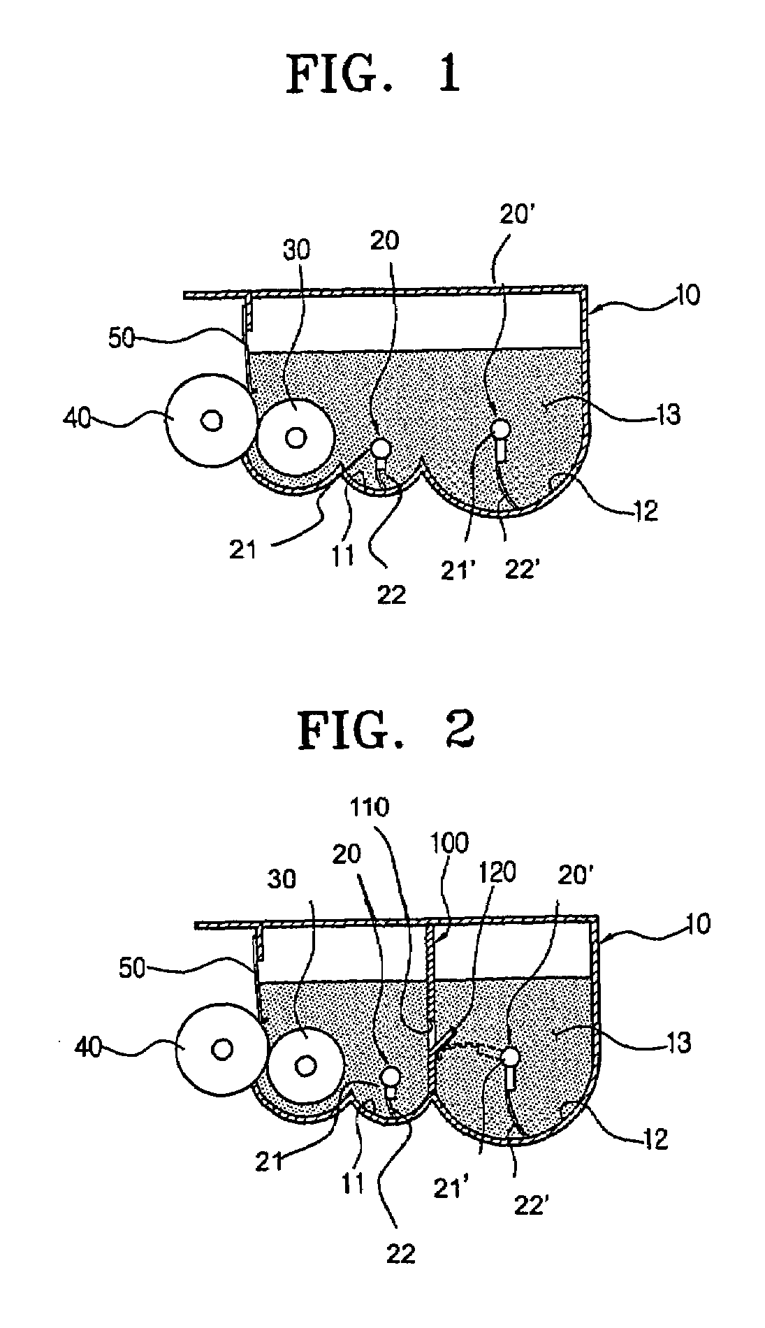
[0026]As shown in FIG. 2, the developing unit of the image forming apparatus according to an embodiment of the present invention includes, a developing casing 10, agitators 20 and 20′, a toner supplying roller 30, a developing roller 40, and a partition 100.

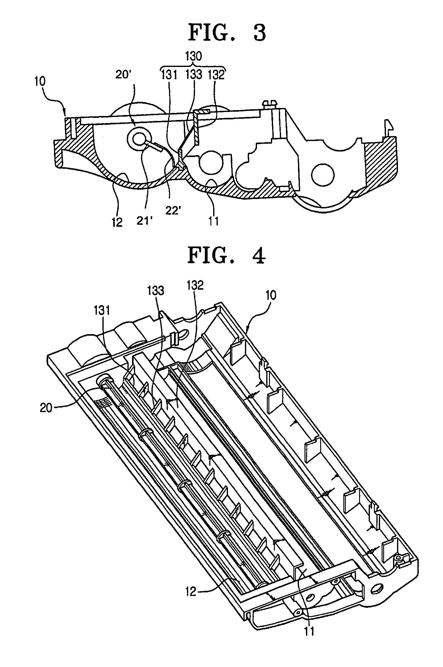
[0027]The developing casing 10 has a plurality of toner chambers, for example, a first toner chamber 11 and a second toner chamber, 12 for containing toner 13. The first and the second toner chambers 11 and 12 are filled with a predetermined quantity of toner 13. The developing casing 10 is sealed so that it does not allow toner leakage from the toner chambers 11 and 12.

[0028]The agitators 20 and 20′ are rotatably d...


PUM


Abstract

A developer for an image forming apparatus includes a developing casing having a plurality of toner chambers to contain toner, an agitator having a resilient wing and rotatably disposed in the toner chamber for agitating and transferring toner, a toner supplying roller rotatably disposed adjacent to one of the toner chambers of the developing casing, a developing roller for transferring and attaching the toner supplied from the toner supplying roller to a photoconductive medium, and a partition disposed in the developing casing to separate the two toner chamber. The partition has a plurality of slits at a center potion to transfer toner from one toner chamber to another toner chamber therethrough, while the agitator rotates. Also, the partition has a rib sloped upward at a predetermined angle from a lower portion of the slit. While the agitator rotates, the resilient wing of the agitator resiliently contacts with the rib so as to splash the toner upward. The toner being splashed then drops due to gravity and moves through the slit.

Description

CROSS-REFERENCE TO RELATED APPLICATIONS[0001]This application claims the priority of Korean Patent Application No. 2003-44707, filed Jul. 2, 2003 in the Korean Intellectual Property Office, the disclosure of which is incorporated herein by reference.BACKGROUND OF THE INVENTION[0002]1. Field of the Invention[0003]The present invention relates to an electrophotographic image forming apparatus, and more specifically, to a developer to develop an electrostatic latent image of a photoconductive medium with a toner.[0004]2. Description of the Related Art[0005]Conventionally, a developer for an image forming apparatus transfers toner from a developing casing to a developing roller using a toner supplying roller. The developing roller rotates and transfers the toner attached to an outer circumference thereof to a photoconductive medium so as to develop an electrostatic latent image of the photoconductive medium. Recently, as the life span and the toner capacity of developers increases, the ...

Claims


Application Information

Patent Timeline
Patent Type & Authority Patents(United States)
IPC IPC(8): G03G15/08G03G15/06
CPCG03G15/0896G03G2215/085G03G2215/0822G03G15/08
Inventor JEON, NAM-GON
Owner S PRINTING SOLUTION CO LTD
Why Eureka
Try Eureka