Positive expiratory pressure device with bypass

a positive expiratory pressure and bypass technology, applied in the field of hand-held, multi-use, single-patient positive oscillatory expiratory pressure respiratory therapy devices, can solve the problems of poor oxygenation, pneumonia and/or death, and achieve the effect of convenient assembly and disassembly of the device for cleaning

Inactive Publication Date: 2006-06-13
SMITHS MEDICAL ASD INC
View PDF33 Cites 123 Cited by
  • Summary
  • Abstract
  • Description
  • Claims
  • Application Information

AI Technical Summary

Problems solved by technology

If these secretions are allowed to remain in the lungs, airway obstruction occurs resulting in poor oxygenation and possible pneumonia and / or death.

Method used


Image

  • Positive expiratory pressure device with bypass
  • Positive expiratory pressure device with bypass
  • Positive expiratory pressure device with bypass

Examples


Embodiment Construction

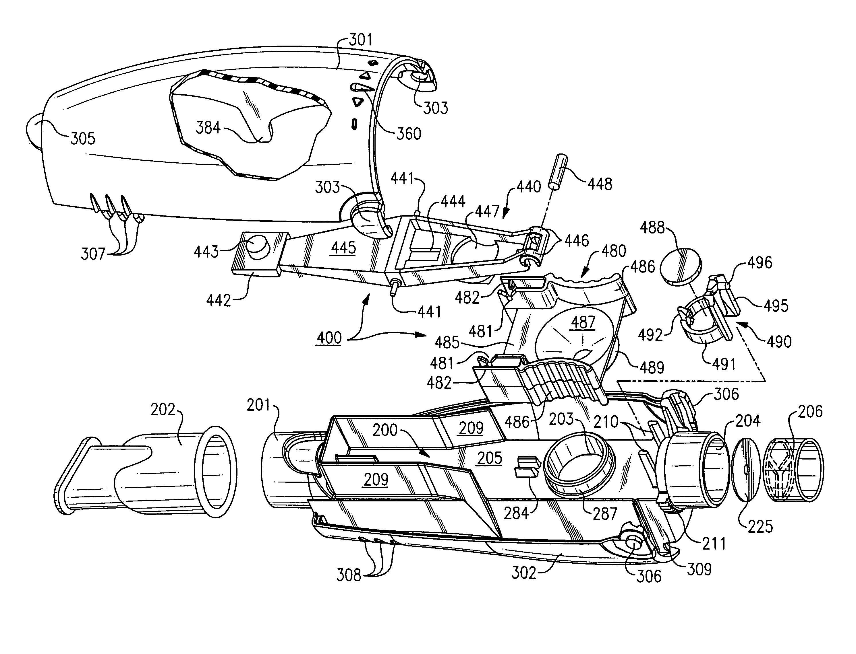
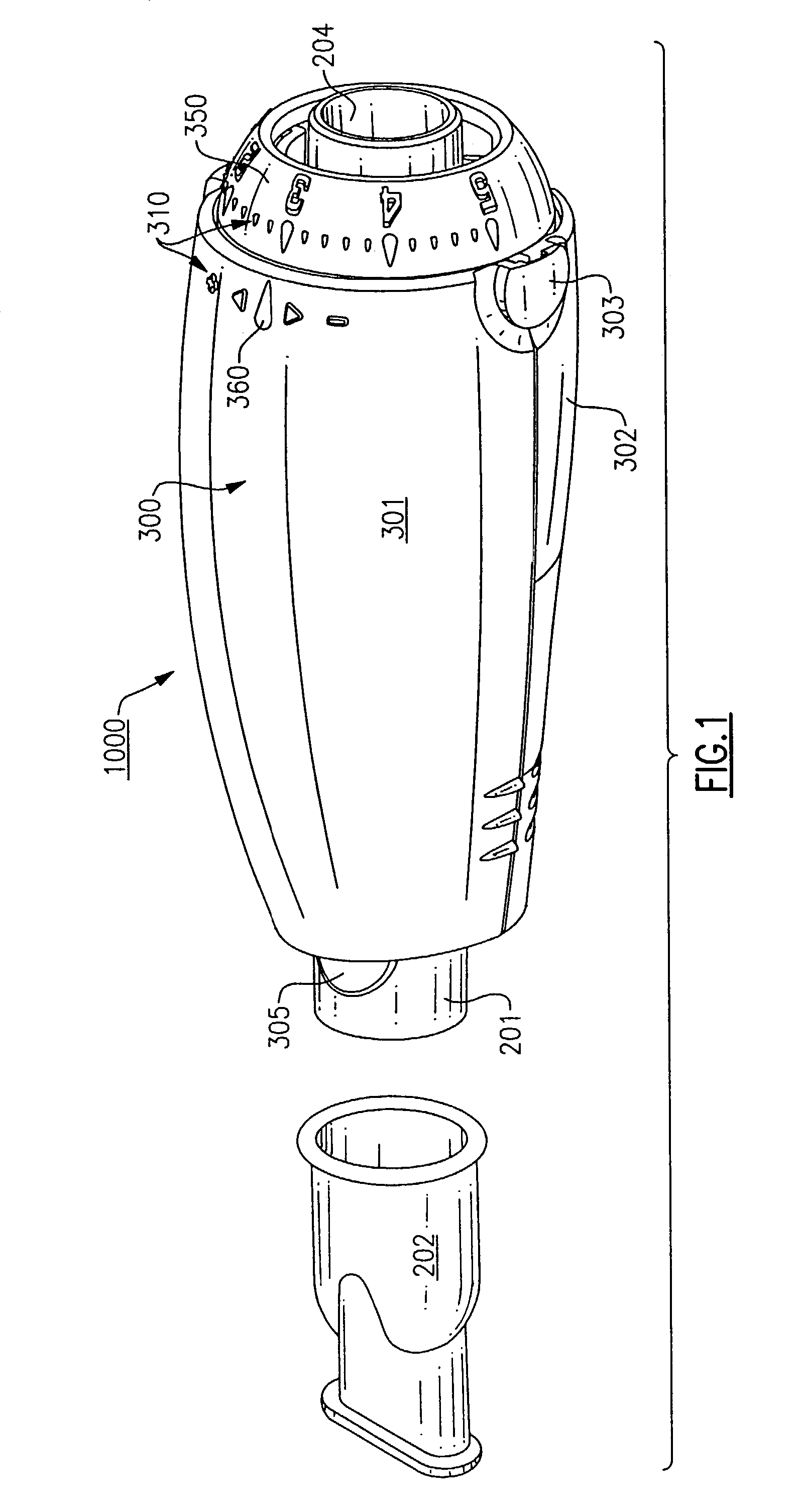
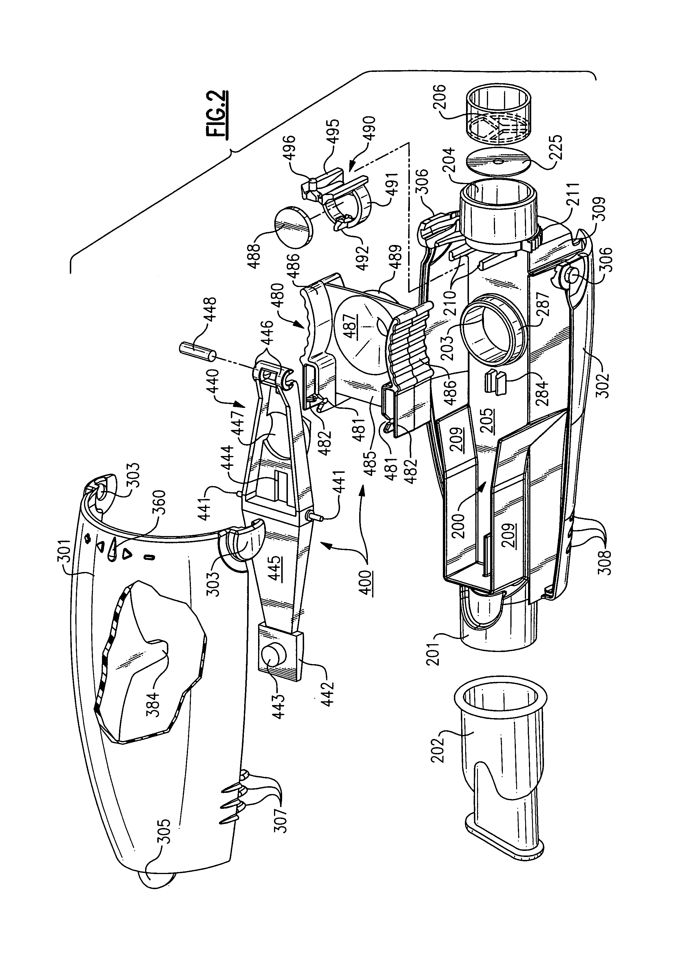
[0022]Referring now to the drawings, there is illustrated in FIGS. 1 and 2 an oscillatory positive expiratory pressure (PEP) respiratory therapy device 1000 for applying oscillatory positive expiratory air pressure (PEP) therapy to a patient. When expiratory air is passed from a patient through an air-flow tube 200 to an expiratory-air-driven oscillatory rocker assembly 400 contained within a two-part housing 300, the expiratory-air-driven oscillatory rocker assembly 400 creates an oscillatory positive expiratory air pressure which is applied to the patient during exhalation. The expiratory-air-driven oscillatory rocker assembly 400 comprises two portions, a rocker portion 440 and a rocker support or platform portion 480 which act together in creating the oscillatory PEP therapy and are best illustrated in FIGS. 2–10. The details of the structure and operation of this oscillatory PEP portion of the device will be described in detail hereinafter.

[0023]To control the magnitude and fre...


PUM


Abstract

A multi-use, hand held, single patient oscillatory positive expiratory pressure respiratory therapy device which is easily assembled and disassembled for cleaning, and which is not position dependent during therapy, but operable through a wide range of device orientation.

Description

[0001]This application is a continuation in part of application Ser. No. 09 / 449,208 filed Nov. 24, 1999, which is now U.S. Pat. No. 6,581,598.BACKGROUND OF THE INVENTION[0002]1. Field of the Invention[0003]This invention relates in general to a hand-held, multi-use, single patient positive oscillatory expiratory pressure respiratory therapy device and, in particular, to an easily assembled and disassembled positive oscillatory expiratory pressure respiratory therapy device which is not position dependent during therapy, but operable through a wide range of device orientation.[0004]2. Description of Related Art[0005]Persons who suffer from mucus-producing respiratory conditions that result in large amounts of mucus being produced in the lungs often require assistance in the removal of these secretions. If these secretions are allowed to remain in the lungs, airway obstruction occurs resulting in poor oxygenation and possible pneumonia and / or death. One of the clinically recognized tr...

Claims


Application Information

Patent Timeline
Patent Type & Authority Patents(United States)
IPC IPC(8): A61M16/00A61M16/08A61M16/20A63B23/18
CPCA61M16/08A61M16/20A61M16/208A63B21/00196A63B23/18A61M16/209A63B21/00076A63B21/00069A61M16/0006A61M16/205A63B2071/0633
Inventor PELEROSSI, RICHARD K.KING, GREGORY S.FORAN, JENNIFER M.WEINSTEIN, LAWRENCE A.RICHARDS, FREDRICK M.ZIRPS, CHRISTOPHER T.ELDEN, ROBERT H.
Owner SMITHS MEDICAL ASD INC
Why Eureka
Try Eureka