Patient interface and non-invasive positive pressure ventilating method

a positive pressure ventilating and patient technology, applied in the field of patient interface and non-invasive positive pressure ventilating method, can solve the problems of increasing the pressure of the mask against the patient's face, reducing the effectiveness of therapy, increasing the speed and noise of the flow generator, etc., to improve therapy to a patient, reduce or eliminate the effect of problems caused by leakag

Active Publication Date: 2009-01-15
RESMED LTD
View PDF18 Cites 162 Cited by
  • Summary
  • Abstract
  • Description
  • Claims
  • Application Information

AI Technical Summary

Benefits of technology

[0008]One aspect of the invention relates to a patient interface that improves therapy to a patient by reducing, or eliminating, problems caused by leakage from the patient interface.
[0009]Another aspect of the invention relates to a patient interface that improves therapy to a patient by reducing, or eliminating, patient discomfort caused by leakage from the patient interface.
[0010]Yet another aspect of the invention relates to a patient interface that reduces, or eliminates, the occurrence of explosive, or bursting, leakage.

Problems solved by technology

Air leakage from between the patient's skin and the patient interface reduces the effectiveness of the therapy.
The air leakage may cause the patient to increase the pressure of the mask against the patient's face.
The air leakage may also cause the flow generator to increase the pressure of the delivered air, thus increasing the speed and noise of the flow generator.
Increasing the pressure of the delivered air results in an increase in the flow of air, including the vent flow and leak flow.
If a humidifier is used, the increase in the leak flow results in a waste of water from the humidifier.
If supplemental oxygen is being provided to the flow of air, the increase in the leak flow causes a waste of some of the supplemental oxygen.
Moreover, the air leakage may act as an irritant to the patient's eyes and disturb the patient's sleep.

Method used


Image

  • Patient interface and non-invasive positive pressure ventilating method
  • Patient interface and non-invasive positive pressure ventilating method
  • Patient interface and non-invasive positive pressure ventilating method

Examples


first embodiment

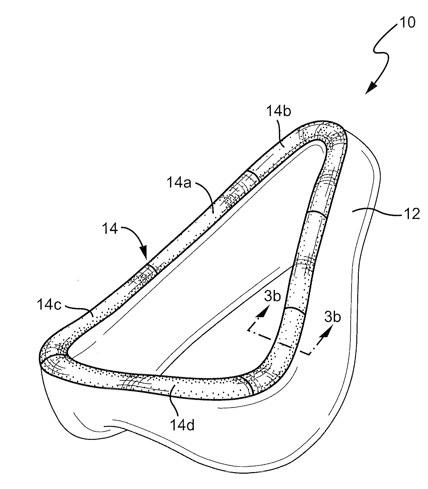
[0057]Referring to FIGS. 3a and 3b, a patient interface 10 according to one embodiment of the invention includes a cushion 12 having a filler layer 14 provided on the cushion 12. The filler layer 14 is adapted to be in contact with the patient's skin. The cushion 12 may be formed of, for example, silicone and the filler layer 14 may be formed of, for example, foam. The filler layer 14 may be, for example, adhesively attached to the cushion 12, for example by glue. The filler layer 14 may also be mechanically connected to the frame of the mask as a skin that envelops the cushion. In that case, the filler layer 14 may be replaced, for example in a manner similar to replacing the foam over earphones. The filler layer 14 may be connected at the same location as the cushion, on the cushion itself, or at another point on the frame. The filler layer 14 may also be silicone foam injected over the silicone cushion 12 so that the cushion and the filler layer are a single object. The filler la...

second embodiment

[0058]As shown in FIG. 4, an interface 22 may include a seal 24 in contact with the patient's skin 20. A diffuser 26 (e.g., of foam material) is provided outside the seal 24 of the interface 22 to increase the resistance to leak flow Q and diffuse any leak flow that may actually occur. The diffuser 26 may be connected to the seal 24 in a manner similar to the connection of the filler layer 14 to the cushion 12 of the first embodiment. However, unlike the first embodiment, in which only the filler layer 14 contact the patient's face, according to the second embodiment the seal 24 of the interface 22 and the diffuser 26 are provided in series and both contact the patient's face. Accordingly, in the second embodiment the “sealing” provided by the seal 24 and diffuser 26 is broader than the “sealing” provided by the first embodiment as the seal 24 and the diffuser increase the resistance to leak flow. It should be appreciated that the seal may provide very little, or no resistance, to l...

third embodiment

[0059]Referring to FIG. 5, an interface 22 includes a primary seal 24 adapted to contact the patient's skin 20. The primary seal 24 may be, for example, silicone. A secondary seal 32 is placed inside the interface 22 and may also be in contact with the patient's face. The secondary seal 32 may be, for example, foam. The space between the primary seal 24 and a secondary seal 32 includes secondary vents 30 which are provided in addition to primary vents 28. A vent flow VF is vented through the primary vents 28. The volume between the primary seal 24 and the secondary seal 32 is vented through secondary vents 30 to create a local low-pressure area near the primary seal 24, i.e. P21. Any leak flow across the secondary seal 32 will be vented through the secondary vents 30. The secondary vents 30 may be placed in an area of the patient interface where the vented leak flow Q will not disturb the patient.


PUM


Abstract

A patient interface for use in delivering a flow of breathable gas to an airway of a patient includes a first seal adapted to contact the patient's face and seal a first space between the patient interface and the patient's face at a first positive pressure; and a second seal adapted to contact the patient's face and seal a second space between the patient interface and the patient's face at a second positive pressure. The first seal also seals the first space from the second space. A leak reducing element may be provided on a seal to reduce and / or diffuse leakage of gas. A vacuum line configured to create a negative pressure may be provided in the second space to remove any gas leaking from the first space to the second space. A seal may be connected to a conduit for delivering the flow of gas that is incorporated into a frame of the patient interface. The seal may be inflatable by the flow of breathable gas to pressurize the seal against the patient's face and include a vent that directs the flow of breathable gas to a space between the patient interface and the patient's face. A cuff may be provided over the seal in the nasal bridge region to direct any leakage of the gas flow from the seal in the nasal bridge region in a direction away from the patient's eyes.

Description

CROSS REFERENCE TO RELATED APPLICATION[0001]This application claims priority to U.S. Provisional Application 60 / 949,692, filed Jul. 13, 2007, the entire contents being incorporated herein by reference.FIELD OF THE INVENTION[0002]Sample embodiments of the present invention relate to a patient interface for use in delivering a flow of breathable gas to an airway of a patient. Sample embodiments of the present invention also relate to a non-invasive positive pressure ventilating method.BACKGROUND OF THE INVENTION[0003]Non-invasive positive pressure ventilation (NIPPV) techniques, such as, for example, the application of continuous positive airway pressure (CPAP) have been used to treat sleep disorder breathing (SDB) such as obstructive sleep apnea (OSA) and other disorders such as chronic obstructive pulmonary disease (COPD) and congestive heart failure (CHF). Apparatuses for applying NIPPV techniques typically include a flow generator, including a blower, and a patient interface. A de...

Claims


Application Information

Patent Timeline
Patent Type & Authority Applications(United States)
IPC IPC(8): A61M16/06
CPCA61M16/06A61M16/0616A61M2205/42
Inventor BRAMBILLA, ENRICODOHERTY, RENEE FRANCESKWOK, PHILIP RODNEY
Owner RESMED LTD
Why Eureka
Try Eureka