System and method for cooling components in an electronic device

a technology of cooling components and electronic devices, applied in the direction of insulated conductors, power cables, cables, etc., can solve the problems of high temperature of certain components of electronic devices, insufficient cooling of certain components of fans, and particularly problematic lack of circulation

Active Publication Date: 2006-06-13
HEWLETT PACKARD DEV CO LP
View PDF8 Cites 63 Cited by
  • Summary
  • Abstract
  • Description
  • Claims
  • Application Information

AI Technical Summary

Problems solved by technology

Unfortunately, these fans do not adequately cool certain components within the electronic devices.
Insufficient air circulation results in higher temperatures for these components.
This lack of circulation is particularly problematic for smaller components, such as random access memory (RAM) modules, chips, and other low profile modules disposed on a circuit board.
In addition, components in an electronic device are often not adequately isolated from one another.
Unfortunately, existing computers generally do not isolate the hot components, such as processors and memory, from one another.
As a result, the fans circulate the air from one set of hot components at least partially over another set of hot components, thereby undesirably heating these neighboring components.
This additional heat can lead to malfunctions and failure of these components.
The problem with this configuration is that the airflow generated by the front fan bypasses the first set of components and circulates the air directly through the rear fan.
As a result, the airflow is inadequate to cool the various components.
The typical solution is to increase the fan speeds to provide the desired airflow, which unfortunately causes higher noise levels within the chassis.

Method used


Image

  • System and method for cooling components in an electronic device
  • System and method for cooling components in an electronic device
  • System and method for cooling components in an electronic device

Examples


Embodiment Construction

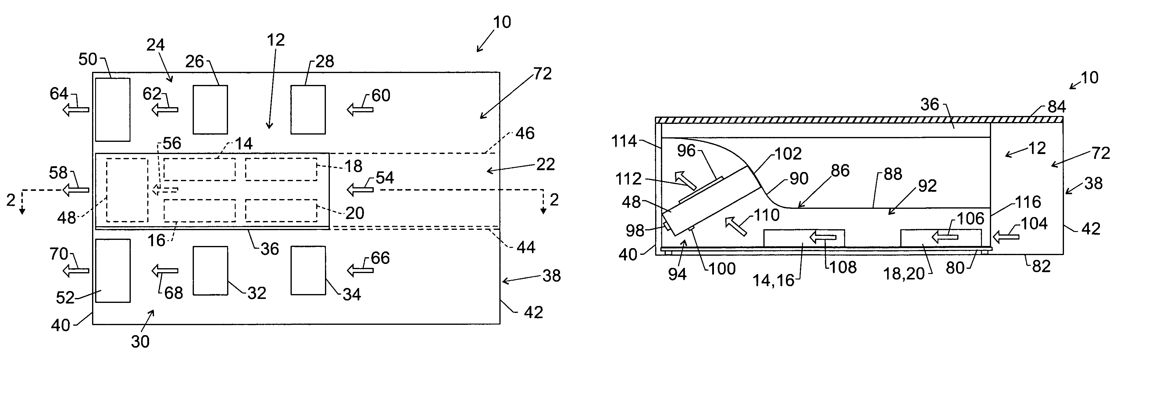
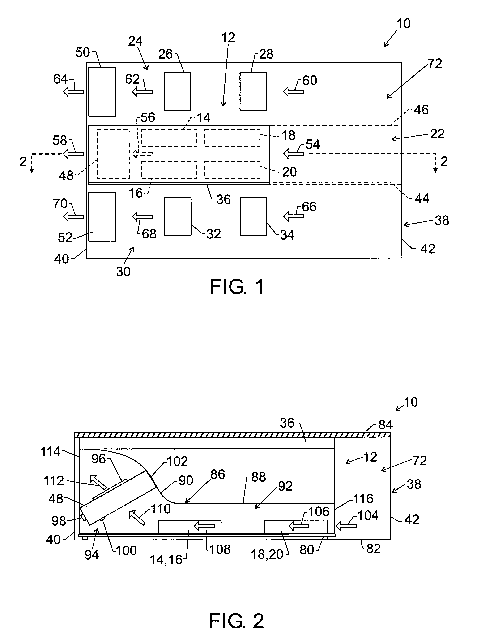
[0016]FIG. 1 is a diagrammatical top view of a system for cooling components of an electric device. The system includes an electronic device 10 having a duct 12 disposed over electronic components 14, 16, 18, and 20 in accordance with embodiments of the present invention. As discussed in further detail below, the duct 12 is configured to isolate different component regions, including a first component region 22 having the electronic components 14, 16, 18, and 20, a second component region 24 having electronic components 26 and 28, and a third component region 30 having electronic components 32 and 34. Moreover, the illustrated duct 12 is configured to focus an airflow around the electronic components 14, 16, 18, and 20. In certain embodiments, the electronic device 10 is a computer, such as a notebook computer, a tablet personal computer, a desktop computer, a server, a network device, or another processor-based device. Embodiments of the electronic components 14, 16, 18, 20, 26, 28...


PUM


Abstract

In certain embodiments, a system for cooling components of an electronic device includes a chassis having a base, sides, and a removable cover disposed over the sides; a first component, a second component, and a third component disposed in the chassis; and a duct disposed in the chassis. In some embodiments, a duct includes a passage, an inlet to the passage, and an outlet from the passage, wherein the passage is disposed over the first component but not over the second and third components; and an upper member disposed against the removable cover lengthwise along the duct, wherein the duct and the upper member are configured to separate the second component from the third component in substantially different regions within the chassis. In particular embodiments, the system also includes a fan disposed angularly in the duct, such that the fan can provide an airflow in an angular direction relative to the first component.

Description

BACKGROUND OF THE RELATED ART[0001]Fans are often disposed in electronic devices, such as computers, to cool the various internal components. Unfortunately, these fans do not adequately cool certain components within the electronic devices. For example, one or more fans are often mounted on a wall of the electronics chassis, yet the airflow provided by these fans circulates over the top of the components rather than across them. Insufficient air circulation results in higher temperatures for these components. This lack of circulation is particularly problematic for smaller components, such as random access memory (RAM) modules, chips, and other low profile modules disposed on a circuit board.[0002]In addition, components in an electronic device are often not adequately isolated from one another. For example, a typical computer includes one or more processors, memory modules, option cards, disk drives, and other electronics, which generate different levels of heat within the computer...

Claims


Application Information

Patent Timeline
Patent Type & Authority Patents(United States)
IPC IPC(8): H05K7/20
CPCH05K7/20727G06F1/20
Inventor TUCKER, SEAN W.SEARBY, TOM J.ROESNER, ARLEN L.
Owner HEWLETT PACKARD DEV CO LP
Why Eureka
Try Eureka