Methods and apparatus for providing a sufficiently stable power to a load in an energy transfer system

a technology of energy transfer system and load, applied in the field of energy transfer methods and equipment, can solve the problems of difficult and/or undesirable to include a substantial and/or long-term source of power, difficulty in implementing a substantial and/or long-term “internal” power source for internally located devices, repeated entry, etc., and achieves the effect of reducing the number of devices in the system

Inactive Publication Date: 2006-06-13
ABIOMED
View PDF17 Cites 119 Cited by
  • Summary
  • Abstract
  • Description
  • Claims
  • Application Information

AI Technical Summary

Problems solved by technology

For example, one or more devices that require power (e.g., electrical, mechanical, optical, and acoustic devices) may be located within the confines of a closed system, or “body,” in which it may be difficult and / or undesirable to also include a substantial and / or long term source of power.
In some cases, such requirements and constraints may make the implementation of a substantial and / or long term “internal” power source for internally located devices problematic.
In some closed systems, repeated entry, into the system may be undesirable for a variety of reasons.
In other closed systems, significant internal power requirements and a limited internal space may prohibit the implementation of a suitably sized internal power source.
In yet other systems, contamination and / or security issues may pose particular challenges in implementing an internal power source.
With respect to the human body, issues such as repeated reentry or surgery, internal space limitations, and contamination (e.g., infection) may make the implementation of a suitable internal power source for some of these implanted devices impractical.
Accordingly, one issue associated with conventional TET devices is that the power supplied by the secondary winding to a load (e.g., an implanted device) may be quite sensitive to more than nominal or trivial physical displacements of either the primary winding or the secondary winding from an optimum coupling position.
Without a consistent power source, the implanted device may function erratically or intermittently.
Such an erratic or intermittent operation can have undesirable, and in some cases serious life threatening effects on the patient.

Method used


Image

  • Methods and apparatus for providing a sufficiently stable power to a load in an energy transfer system
  • Methods and apparatus for providing a sufficiently stable power to a load in an energy transfer system
  • Methods and apparatus for providing a sufficiently stable power to a load in an energy transfer system

Examples


Embodiment Construction

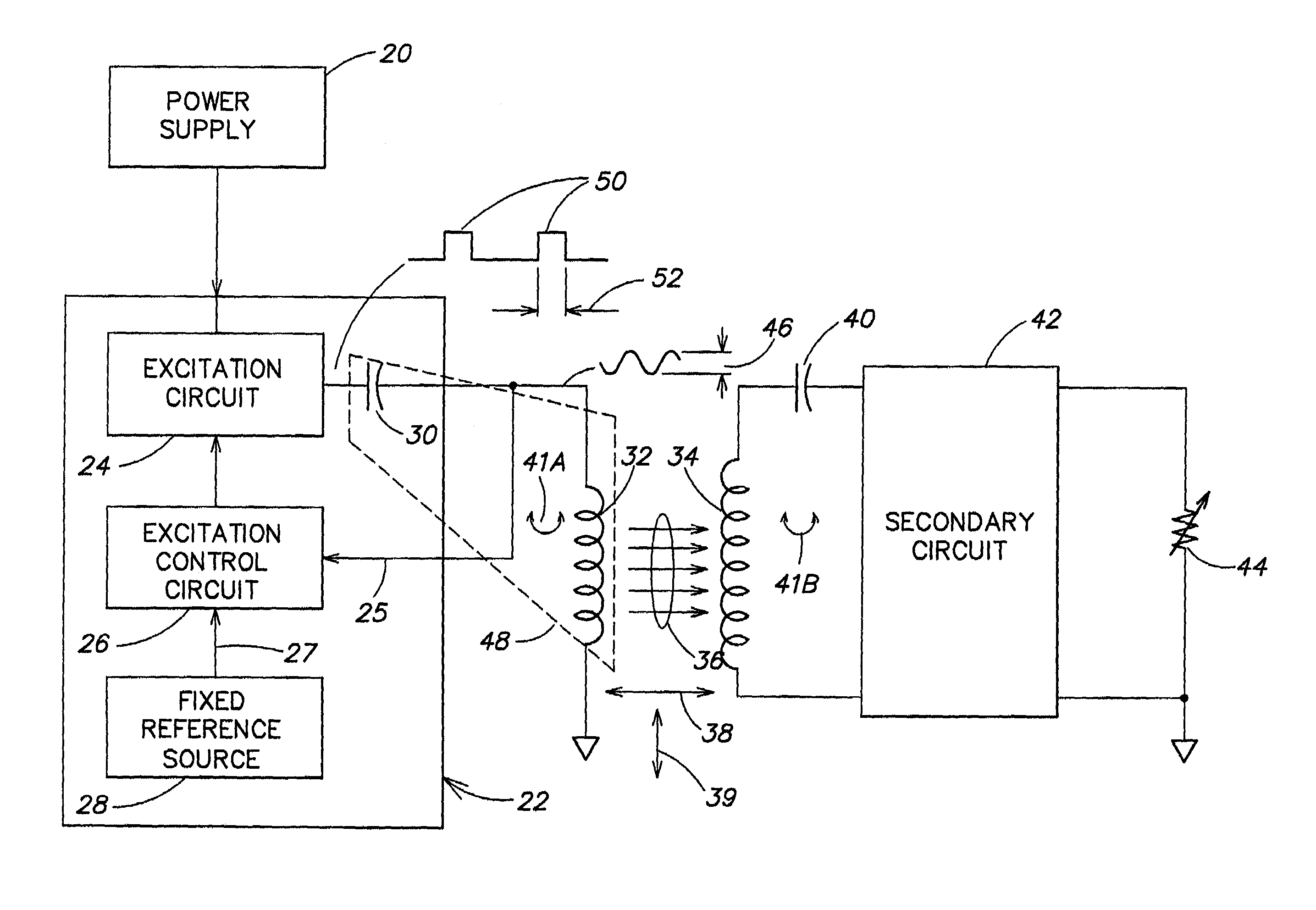
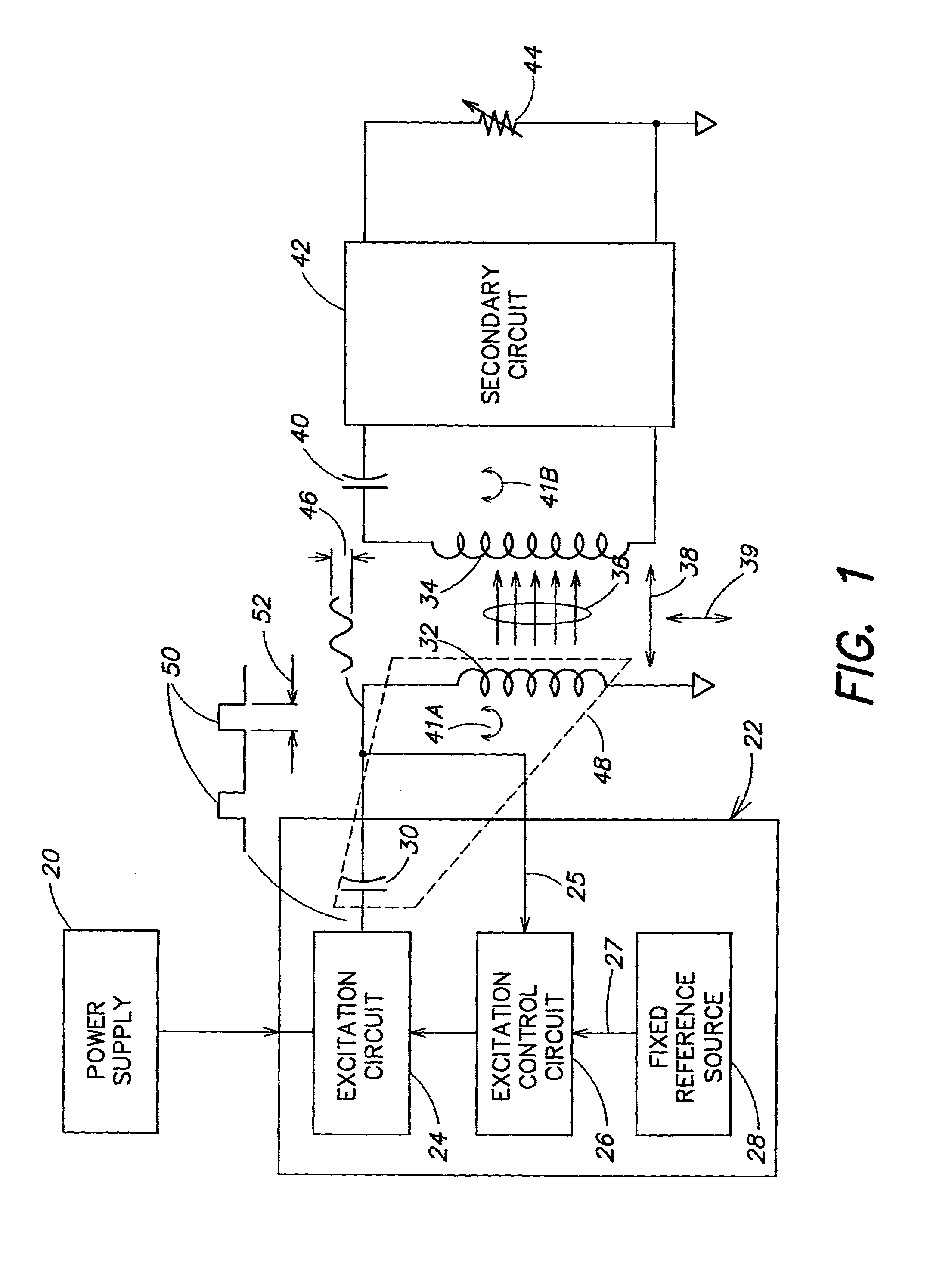
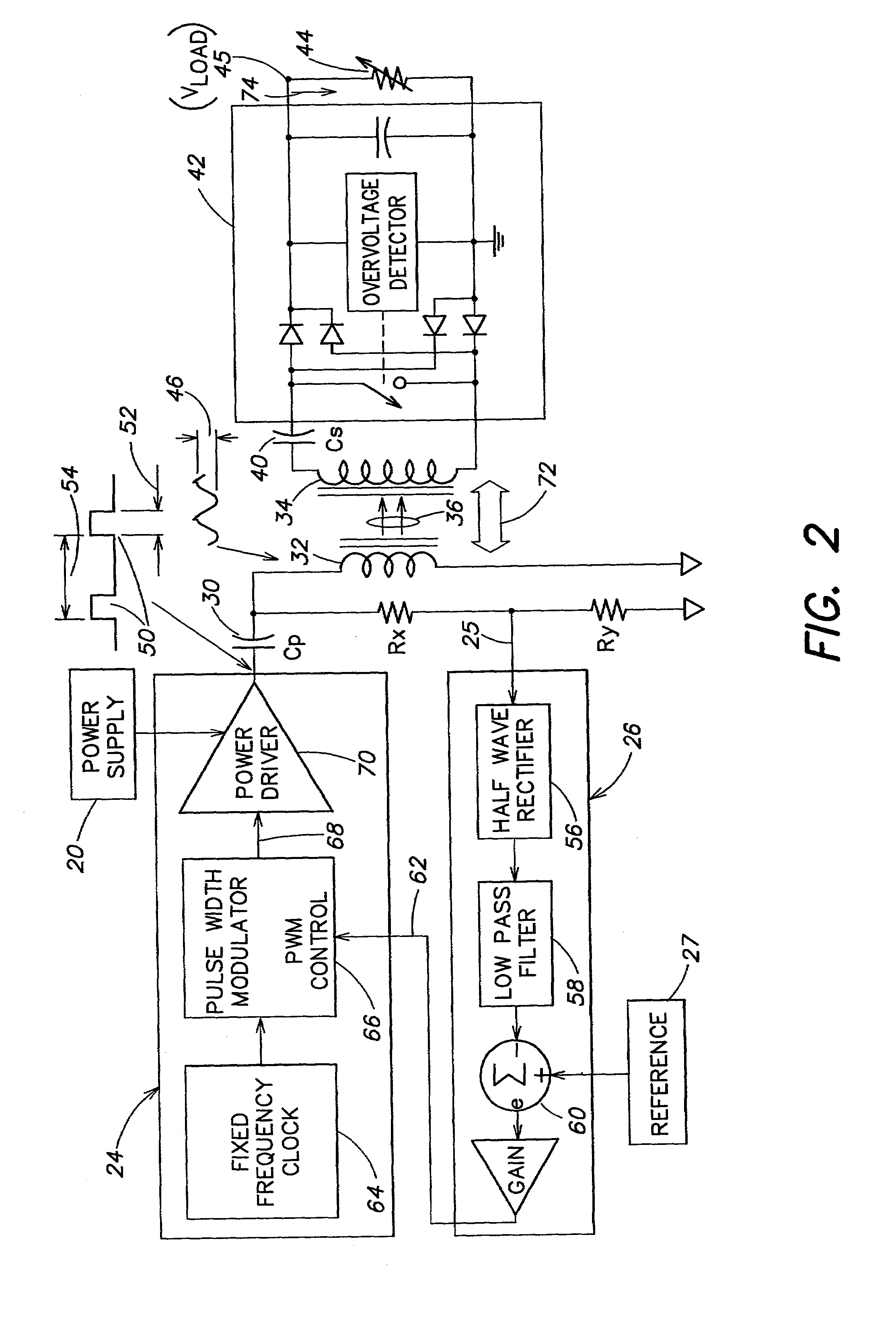
[0032]One embodiment of the present invention is directed to methods and apparatus for providing a sufficiently stable power to a load in an energy transfer system. In one aspect of this embodiment, the energy transfer system may transfer energy across a physical boundary. The boundary may be formed, for example, by some inanimate material or living tissue and may be in a solid, liquid or gaseous phase. The boundary may also be formed by a combination of inanimate materials or living tissue in various phases. In another aspect, the boundary may be arranged to form a closed system (e.g., the boundary may completely surround a “body”), and the energy transfer system may be implemented so as to transfer energy, from a position external to the body, across the boundary to a position internal to the body. The transferred energy may be used to provide power to one or more devices located internal to the body. One example of an application of such an energy transfer system is providing pow...


PUM


Abstract

Methods and apparatus for providing a sufficiently stable power to a load in an energy transfer system that transfers energy from one side of a physical boundary to another side of he boundary. In one example, a power supply and a primary winding are located on a first side of a physical boundary (e.g., external to a body), and a secondary winding and the load are located on a second side of the physical boundary (e.g., internal to the body). A primary voltage across the primary winding is regulated so as to provide a sufficiently stable output power to the load notwithstanding changes in the load and / or changes in a relative position of the primary winding and the secondary winding. One aspect of the invention relates to energy transfer methods and apparatus for use in connection with the human body. In particular, one example of the invention includes a transcutaneous energy transfer (TET) system for transferring power from a power supply external to the body to a device implanted in the body.

Description

CROSS REFERENCE TO RELATED APPLICATIONS[0001]This application is a continuation application of U.S. patent application Ser. No. 09 / 635,050 filed Aug. 9, 2000 now U.S. Pat. No. 6,442,434 entitled “METHODS AND APPARATUS FOR PROVIDING A SUFFICIENTLY STABLE POWER TO A LOAD IN AN ENERGY TRANSFER SYSTEM,” and naming as inventors Farhad Zarinetchi and Stephen J. Keville, which application claims the benefit, under 35 U.S.C. § 119(e), of U.S. Provisional Application Ser. No. 60 / 160,343, filed Oct. 19, 1999, entitled “ADAPTIVE TET SYSTEM,” which application is hereby incorporated by reference and U.S. Provisional Application Ser. No. 60 / 223,787, filed Aug. 8, 2000, entitled “ADAPTIVE TET SYSTEM,” both of which are hereby incorporated by reference.BACKGROUND OF THE INVENTION[0002]1. Field of the Invention[0003]The present invention relates to energy transfer methods and apparatus. More particularly, the invention relates to providing a sufficiently stable power to a load in an energy transfer...

Claims


Application Information

Patent Timeline
Patent Type & Authority Patents(United States)
IPC IPC(8): A61N1/18A61M1/12A61N1/372A61N1/378H02J5/00
CPCA61M1/127H02J5/005A61N1/3787Y10S323/911A61M2205/8243H02J50/80H02J50/90H02J50/12A61M60/873A61M60/178A61M60/165A61M60/196A61M60/216H02J2310/23A61N1/00
Inventor ZARINETCHI, FARHADKEVILLE, STEPHEN J.
Owner ABIOMED
Why Eureka
Try Eureka