Building block

a technology of building blocks and connecting parts, applied in the field of building blocks, can solve the problems of limited connection methods, limited shapes formed from assembling these building blocks, and the 679,780 are therefore less attractive and less competitive in the existing commercial environmen

Inactive Publication Date: 2006-06-20
YOUTH TOY ENTERPRISE
View PDF5 Cites 37 Cited by
  • Summary
  • Abstract
  • Description
  • Claims
  • Application Information

AI Technical Summary

Benefits of technology

[0005]A primary object of the present invention is to provide a building block that has a structure allowing a plurality of the building blocks to connect together in more different manners, so that more changeful shapes could be formed to create more fun.

Problems solved by technology

Since the building blocks disclosed in U.S. Pat. No. 6,679,780 must be connected or stacked through full contact of two complete sides on two different building blocks, only limited connecting manners could be employed and only very limited shapes could be formed from assembling of these building blocks.
The building blocks of U.S. Pat. No. 6,679,780 are therefore less attractive and less competitive in the existing commercial environments.

Method used


Image

  • Building block
  • Building block
  • Building block

Examples


first embodiment

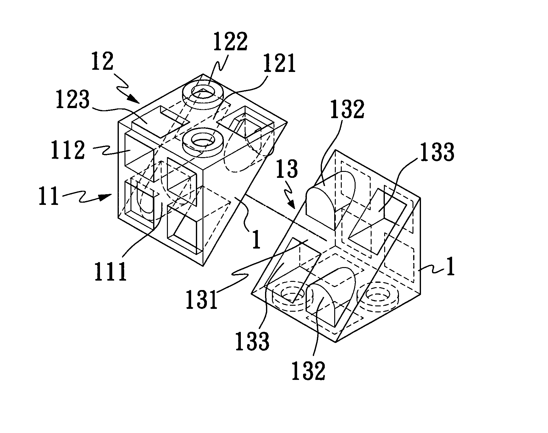
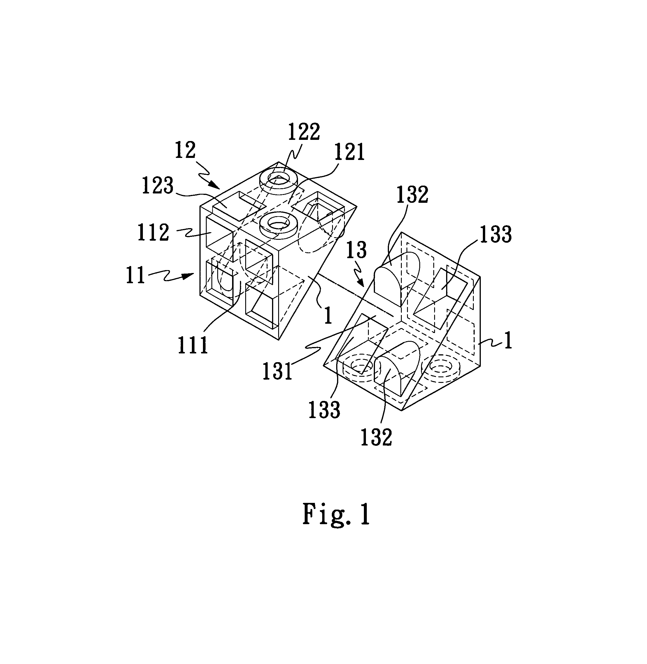
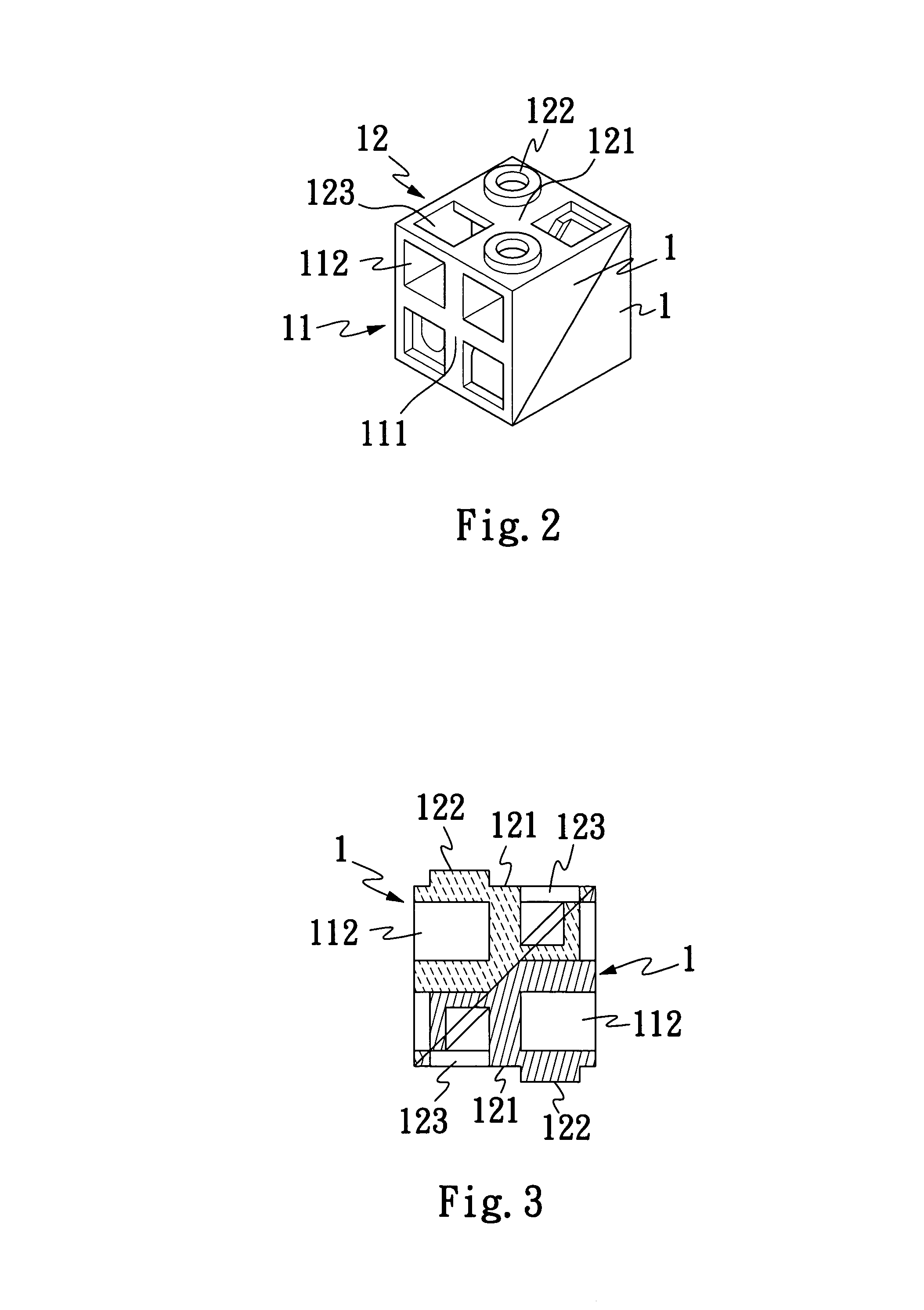
[0021]Please refer to FIG. 1 in which two pieces of building block 1 according to the present invention are shown in two opposite directions, and to FIGS. 2 and 3 that are perspective and sectional views, respectively, showing the two building blocks 1 of FIG. 1 are connected to each other at respective hypotenuse frames thereof.

[0022]As shown, each of the building blocks 1 includes a first and a second square frame 11, 12 perpendicularly connected to each other at inner edges thereof, and a hypotenuse frame 13 extended between outer edges of the first and the second frame 11, 12, such that an isosceles right triangle is formed at each lateral side of the perpendicularly connected first and second square frames 11, 12 of the building block 1. The first and second square frames 11, 12 and the hypotenuse frame 13 respectively have an outer frame portion and a cross-shaped rib portion 111, 121, 131 located within the outer frame portion. These cross-shaped rib portions 111, 121, 131 ha...

second embodiment

[0024]FIG. 9 shows two pieces of building block 2 according to the present invention viewed from two opposite directions, and FIGS. 10 and 11 are perspective and sectional views, respectively, showing the two building blocks 2 of FIG. 9 are connected to each other at respective hypotenuse frames.

[0025]As can be clearly seen from FIGS. 9, 10, and 11, the building block 2 according to the second embodiment of the present invention includes a first and a second square frame 21, 22 perpendicularly connected to each other at inner edges thereof, and a hypotenuse frame 23 extended between outer edges of the first and the second frame 21, 22, such that an isosceles right triangle is formed at each lateral side of the perpendicularly connected first and second square frames 21, 22 of the building block 2. The first and second square frames 21, 22 and the hypotenuse frame 23 respectively have an outer frame portion and a cross-shaped rib portion 211, 221, 231 located within the outer frame p...


PUM


Abstract

A building block includes two perpendicularly connected square frames, and a hypotenuse frame extended between outer edges of the two square frames. Each of the square and hypotenuse frames has an outer frame portion and an inner cross-shaped rib portion having a thickness twice as large as that of the outer frame portion. The cross-shaped rib portion divides a space enclosed in each frame into four equal divisions, which are four cavities on one of the two square frames; two diagonally opposite round connecting posts and two diagonally opposite cavities on the other square frame; and two diagonally opposite connecting protrusions and two diagonally opposite rectangular cavities on the hypotenuse frame, so that a plurality of the building blocks could be assembled together in different manners to form changeful shapes via engagement of the cavities with corresponding connecting posts or protrusions.

Description

FIELD OF THE INVENTION[0001]The present invention relates to a building block, and more particularly to building blocks that could be linearly and / or angularly connected to one another in different manners to show changeful shapes.BACKGROUND OF THE INVENTION[0002]U.S. Pat. No. 6,679,780 discloses a cubic building block formed from a plurality of connected frame portions having a predetermined thickness. The building block is provided at each side with a cross-shaped rib portion having a thickness smaller than that of the frame portion, so that a space enclosed in each frame portion is divided into four squared cavities. The building block is also provided in the frame portion on at least one side thereof with two diagonally opposite round connecting posts, so that the two round connecting posts respectively have a center just located at a center of a corresponding square cavity on any other side of the building block, and a diameter equal to each side of the squared cavity. When any...

Claims


Application Information

Patent Timeline
Patent Type & Authority Patents(United States)
IPC IPC(8): A63H33/00A63F9/12
CPCA63H33/086
Inventor LIN, FU-CHI
Owner YOUTH TOY ENTERPRISE
Why Eureka
Try Eureka