
Curved beam aircraft passenger seat

a passenger seat and curved beam technology, applied in the field of aircraft passenger seats, can solve the problems of increasing the weight of the seat and limiting the available space for passengers

Active Publication Date: 2006-06-27
BE AEROSPACE INCORPORATED
View PDF13 Cites 33 Cited by
  • Summary
  • Abstract
  • Description
  • Claims
  • Application Information

AI Technical Summary

Problems solved by technology

This arrangement of the supporting structure of the seat increases the seat's weight and limits the available space for passengers.

Method used


Image

  • Curved beam aircraft passenger seat
  • Curved beam aircraft passenger seat
  • Curved beam aircraft passenger seat

Examples


Embodiment Construction

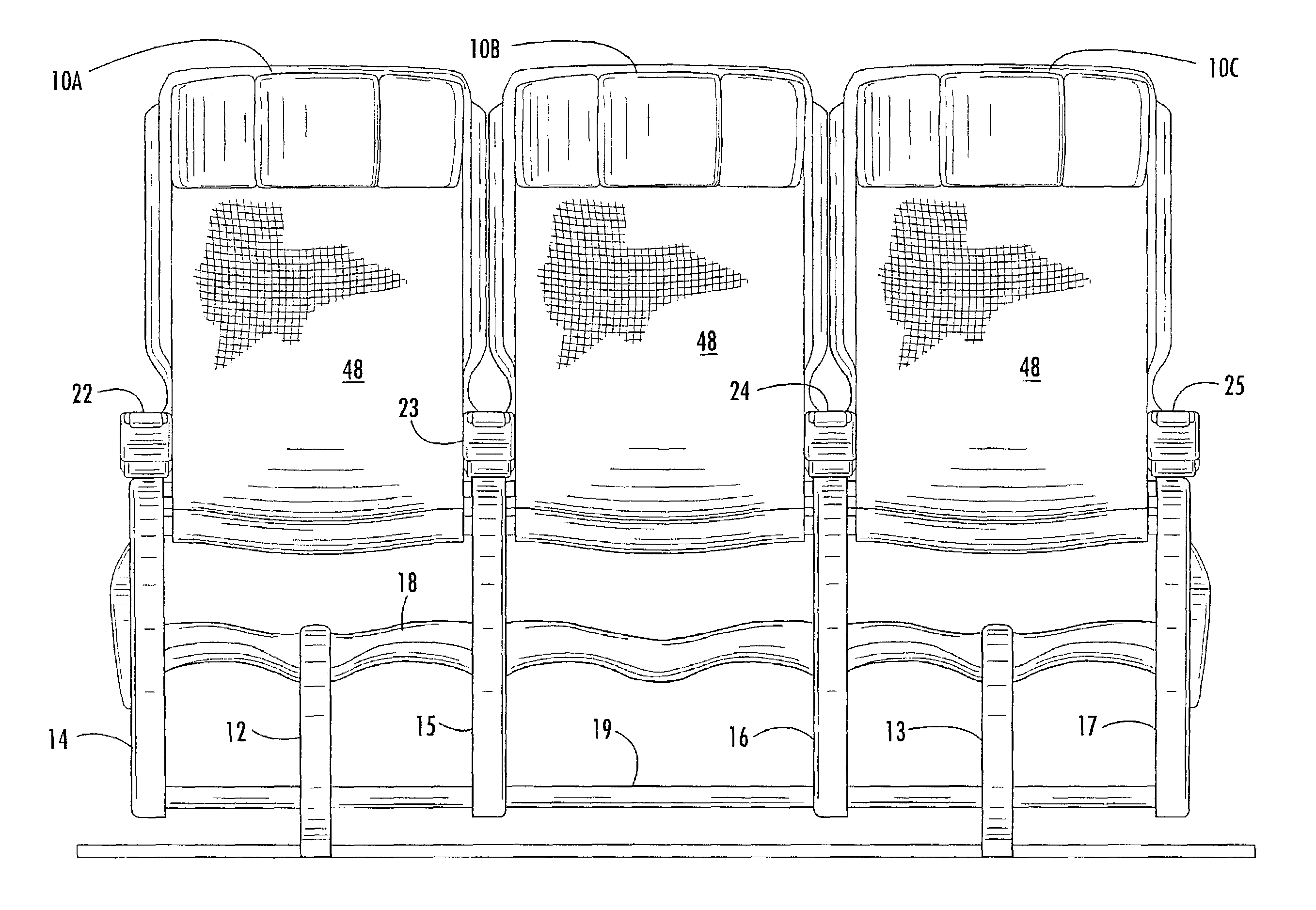
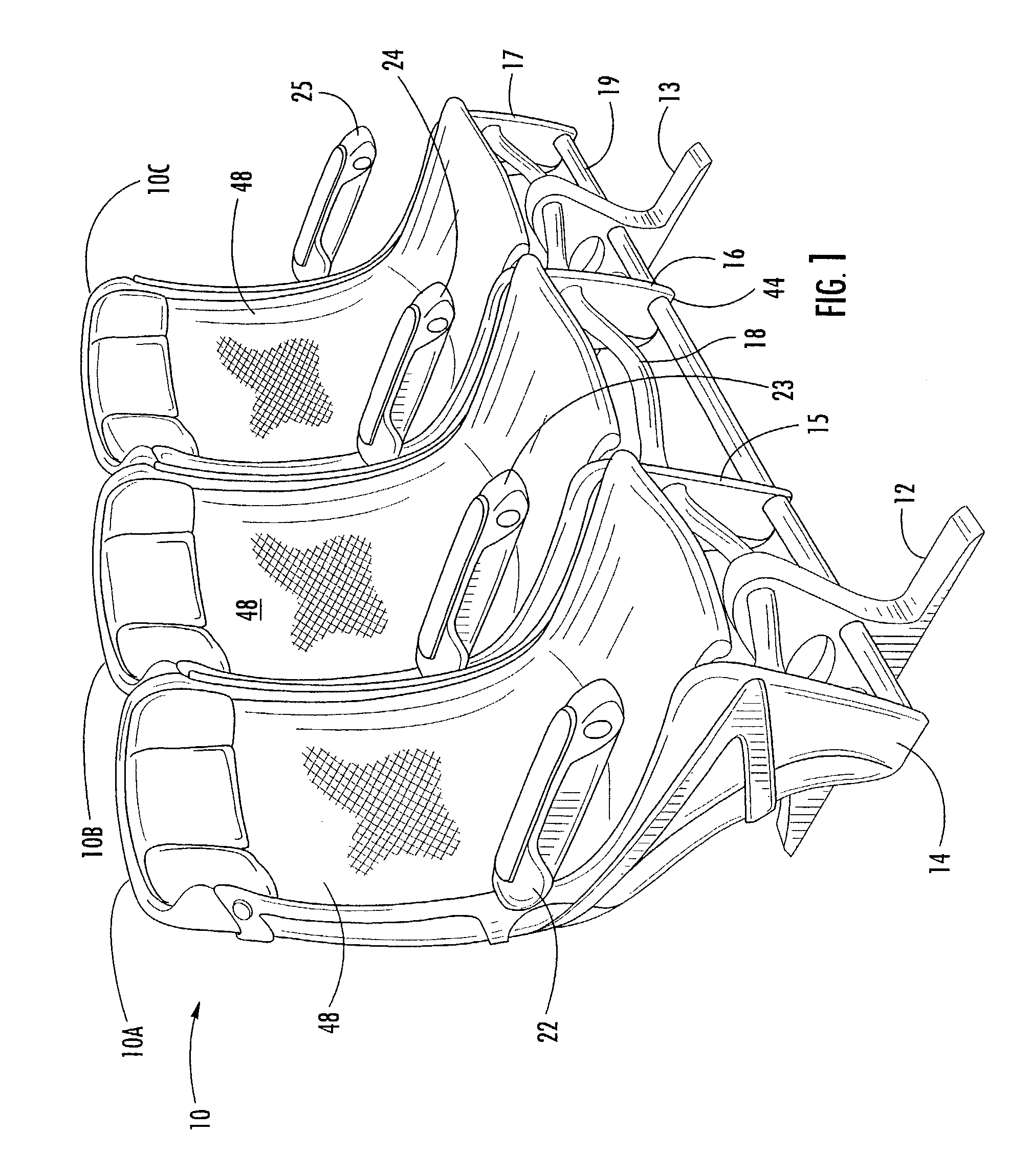
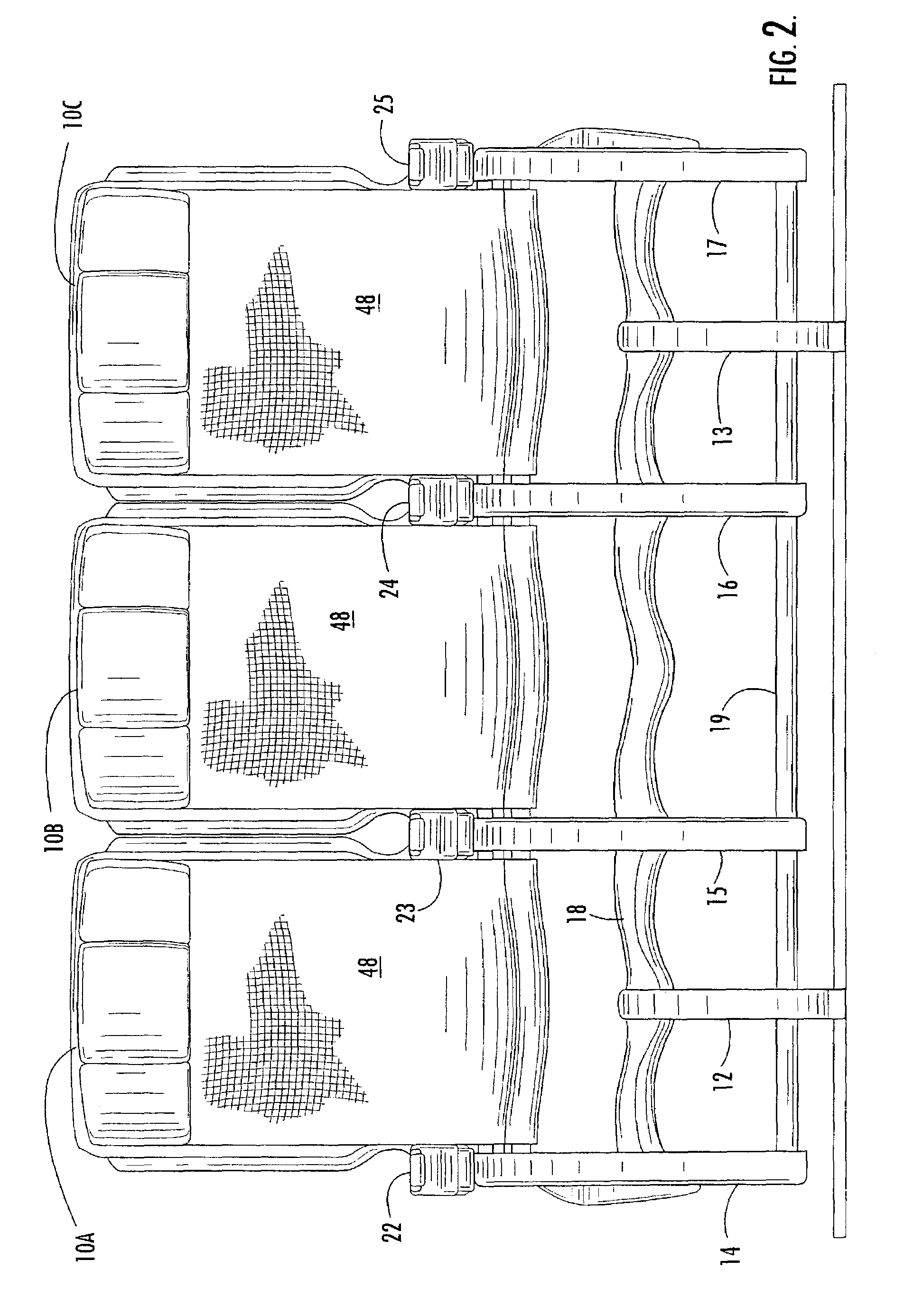
[0029]Referring now specifically to the drawings, a three-seat set according to the present invention is illustrated in FIGS. 1 and 2 and shown generally at reference numeral 10 and comprises individual joined seats 10A, 10B, 10C that are movable from an upright to a recline position without encroaching on an aft-seated passenger. This type of seating is conventionally referred to as “coach” or “main cabin” seating as distinct from larger and more complex first class or business class seating. As will be seen below, the features of this invention are also applicable to first and business class seating. The seat set 10 includes a seat base 11. The seat base 11 includes a pair of leg assemblies 12 and 13 for being attached to a supporting surface by means of conventional track fittings such as disclosed in applicant's U.S. Pat. Nos. 4,776,533; 5,169,091 and 5,871,318. Four seat frames 14, 15, 16 and 17 are connected by single laterally-extending beam 18. A baggage guard rail 19 preven...


PUM


Abstract

A beam for a passenger seat has a hollow body including several spaced-apart frame mounting portions each defining a cross-section for being mounted to a seat frame. Seat portions are disposed between consecutive ones of the frame mounting portions and define a second cross-section for being mounted to a seat base disposed centrally below adjacent pairs of seat frames. The body is curved such that the seat portions are laterally downwardly offset from the frame mounting portions.

Description

TECHNICAL FIELD AND BACKGROUND OF THE INVENTION[0001]This invention relates to an aircraft passenger seat, particularly an aircraft passenger seat in which a single structural beam extends laterally across the front of the seat. Aircraft passenger seats are typically constructed from modular components, the size, weight and construction of which are dictated by many considerations, including fuselage dimensions, aesthetic and safety considerations. Many of these requirements are imposed by law or regulation. The lower seat chassis is constructed of leg modules, while the upper seat is constructed of section assembly modules. In prior art seating systems the leg modules and section assembly modules are connected by mounting both to a pair of parallel beams that extend laterally from one side of the seat or seat assembly to the other. This arrangement of the supporting structure of the seat increases the seat's weight and limits the available space for passengers.[0002]Accordingly, th...

Claims


Application Information

Patent Timeline
Patent Type & Authority Patents(United States)
IPC IPC(8): A47C7/02A47C5/04B64D11/06
CPCA47C5/043B64D11/0696B64D11/06B64D11/0648B64D11/0649
Inventor JOHNSON, GLENN A.
Owner BE AEROSPACE INCORPORATED
Learn More