
Machine for vertical casting of metal

a technology for metal casting and metal casting, applied in the field of metal casting machines, can solve the problems of small technological development and modest technological development of casting machines, and achieve the effect of light weight and strong structur

Inactive Publication Date: 2006-07-11
HEGGSET ENG
View PDF2 Cites 0 Cited by
  • Summary
  • Abstract
  • Description
  • Claims
  • Application Information

AI Technical Summary

Benefits of technology

"The present invention is a machine that allows for easy positioning and maintenance of molds in a safe distance from the casting area. The machine has a compact structure with a small number of components, and is stable and simple to operate. It also allows for easy supply of cooling water and good accessibility for maintenance and repair of molds. The machine has a frame that can pivot horizontally and vertically, making it ideal for positioning and maintenance of molds. The machine is designed to be easily moved and positioned, and to provide a safe and stable working environment for casting molds."

Problems solved by technology

However, a rather modest technological development has taken place in this field during the last 30 years as far the machines are concerned.
Thus, the technological development as regards the casting machines has been very small compared with the results achieved by the development of the mold technology.

Method used


Image

  • Machine for vertical casting of metal
  • Machine for vertical casting of metal
  • Machine for vertical casting of metal

Examples


Embodiment Construction

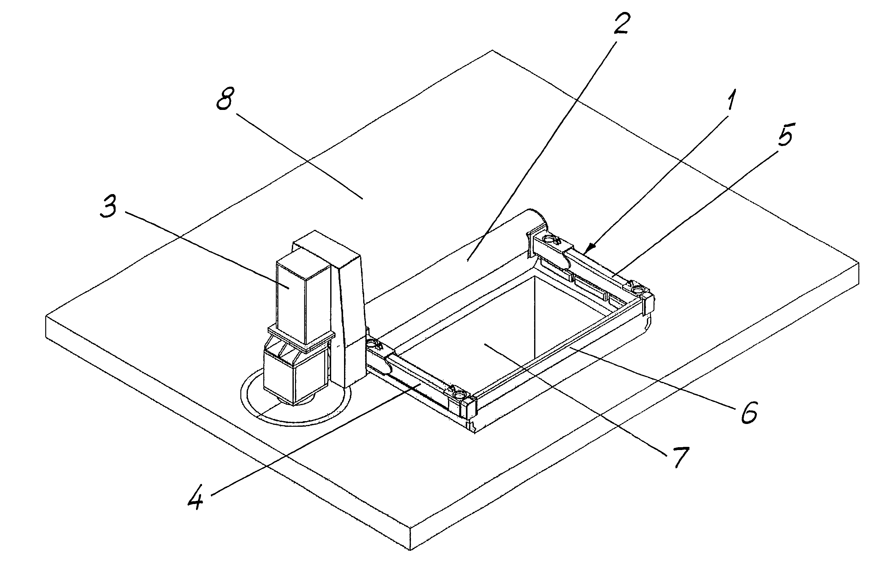
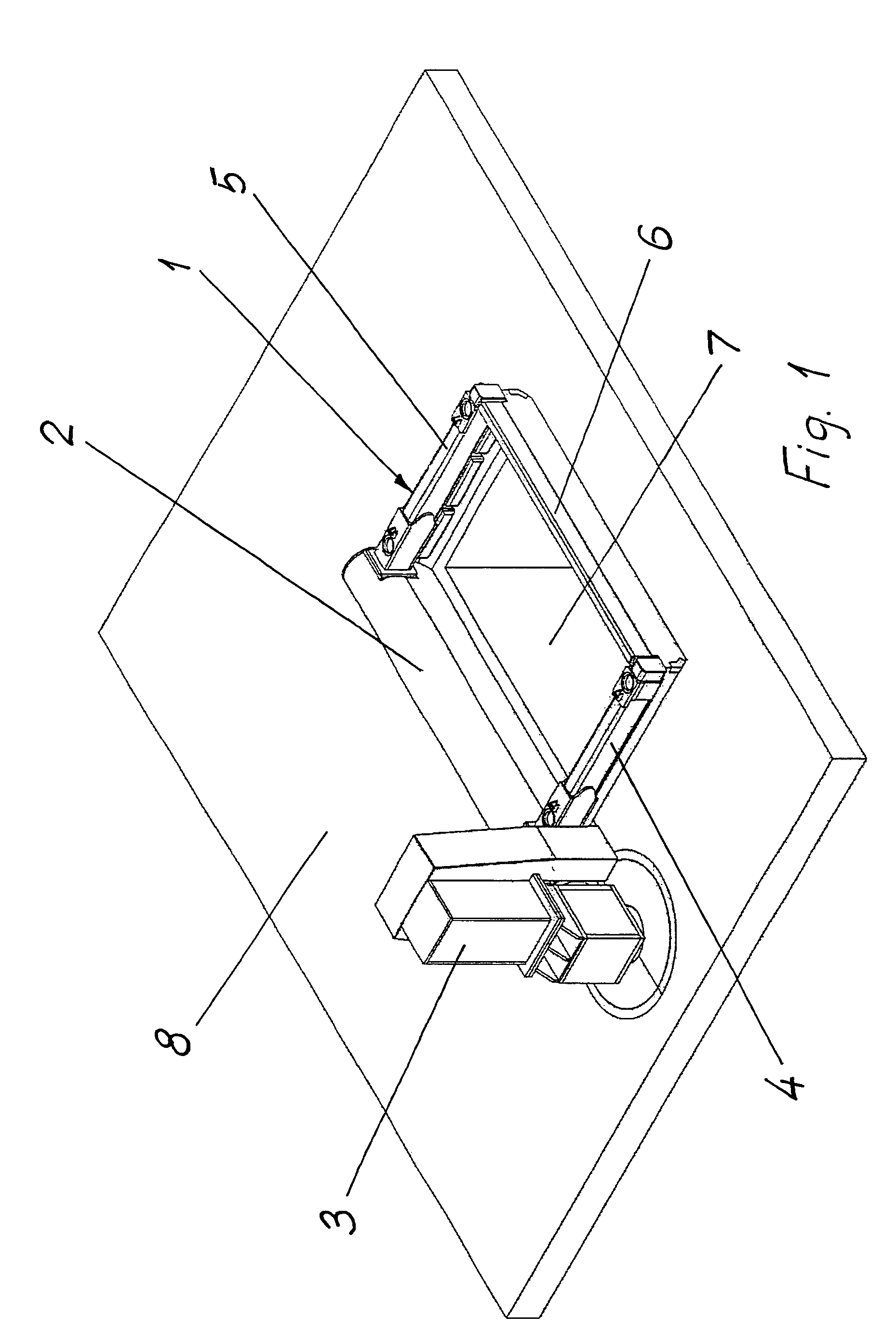
[0026]The invention will in the following be explained more detailed by means of examples, shown in the accompanying drawings.

[0027]FIG. 1 shows the frame in a position above a pit. The casting molds will be mounted on the frame.

[0028]FIG. 2 shows the frame pivoted up to a vertical position. The pit is accessible for lifting out cast bolts or ingots.

[0029]FIG. 3 shows the frame pivoted 90 degrees counterclockwise from the position shown in FIG. 2, ready for maintenance of molds.

[0030]FIG. 4 shows in an elevational view and partly in a vertical section the structure of a support and a frame.

[0031]FIG. 5 shows the support and the frame seen from above.

[0032]FIG. 6 shows the support and the frame in an elevational view, seen in a 90 degrees angle relatively to FIG. 4, wherein the cantilever arm is shown in a cross section.

[0033]FIG. 7 shows in an elevational view and partly in a vertical section the structure of components of the support, correspondingly as shown in FIG. 4, but in a la...


PUM

PropertyMeasurementUnit
angleaaaaaaaaaa
lengthsaaaaaaaaaa
sizeaaaaaaaaaa

Abstract

A machine for vertical casting of metal, including a frame on which casting molds can be mounted and through which cooling water can be supplied during casting. The frame includes a horizontal cantilever arm protruding from a support and being journalled in the support with one end, for vertical pivoting of the frame, said support being rotatable about a vertical axis for horizontal pivoting of the frame.

Description

BACKGROUND OF THE INVENTION[0001]The present invention relates to a machine for vertical casting of metal, comprising a frame on which casting molds can be mounted and through which cooling water can be supplied during casting.PRIOR ART[0002]Machines of this kind usually comprise a rectangular frame. During casting the frame of the machine is horisontal. The frame can be pivoted up to a vertical position, in order to expose the cast items, such as bolts, for their removal. For this purpose the frame may be pivotably journalled at each end of one side of the frame.[0003]The casting is carried out by supplying liquid metal to the casting molds on the frame. Simultaneously, cooling water is supplied for rapid cooling of the metal coming vertically down from the casting molds. The bolts are resting on a vertically movable table which is lowered during the casting. In this manner bolts having lengths of several meters can be cast.[0004]An example of this casting technology is disclosed i...

Claims


Application Information

Patent Timeline
Patent Type & Authority Patents(United States)
IPC IPC(8): B22D11/00B22D11/04B22D11/041B22D11/055B22D15/04
CPCB22D11/055
Inventor HEGGSET, BJARNE A.
Owner HEGGSET ENG
Learn More