Arbor for hole cutter and related method of use

a hole cutter and a technology of a bore bore are applied in the field of bore bores, which can solve the problems of off-axis wobble of the bore bore saw, reducing the cutting life of the hole, and gap formed between the end plate of the saw and the pin ring of the bore bor

Active Publication Date: 2006-07-11
BLACK & DECKER INC
View PDF61 Cites 46 Cited by
  • Summary
  • Abstract
  • Description
  • Claims
  • Application Information

AI Technical Summary

Benefits of technology

[0014]One advantage of the present invention is that the axial bearing surface of the pin ring abuttingly engages the hole cutter and thereby eliminates any gap therebetween that otherwise would cause off-axis wobble.

Problems solved by technology

One of the drawbacks associated with this type of arbor is that when the hole saw is backed away from the shoulder to align the drive pins with the drive holes of the saw, a gap is formed between the end plate of the saw and the pin ring of the arbor.
This gap can lead to off-axis wobble of the hole saw, particularly with larger diameter hole saws and / or hole saws that operate at relatively high rotational speeds.
Off-axis wobble can cause undesirable vibration of the hole saw during cutting that can reduce the cutting life of the hole saw and / or create a degree of inaccuracy in the cut that is greater than otherwise desired.

Method used


Image

  • Arbor for hole cutter and related method of use
  • Arbor for hole cutter and related method of use
  • Arbor for hole cutter and related method of use

Examples


Embodiment Construction

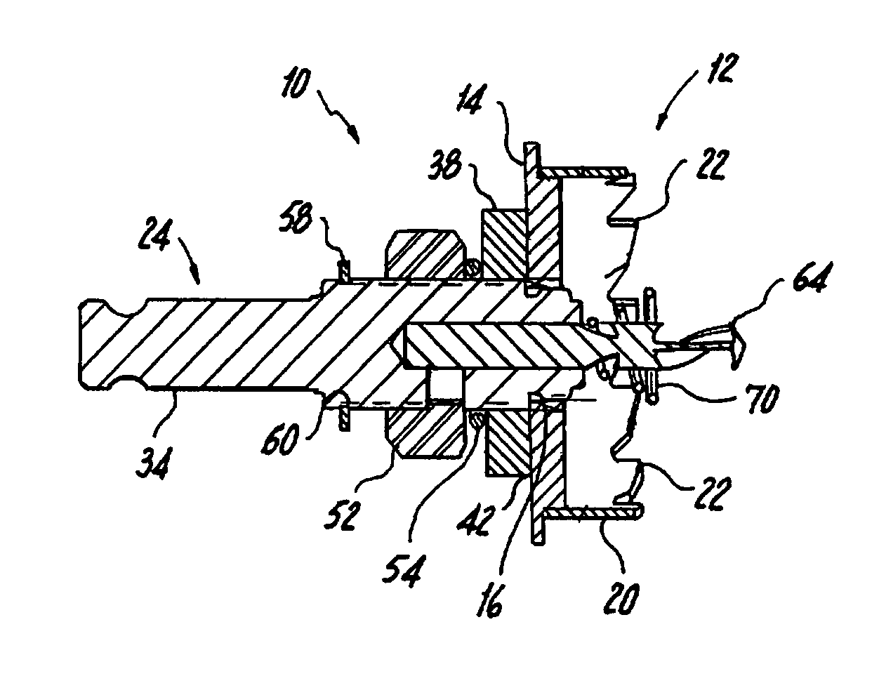
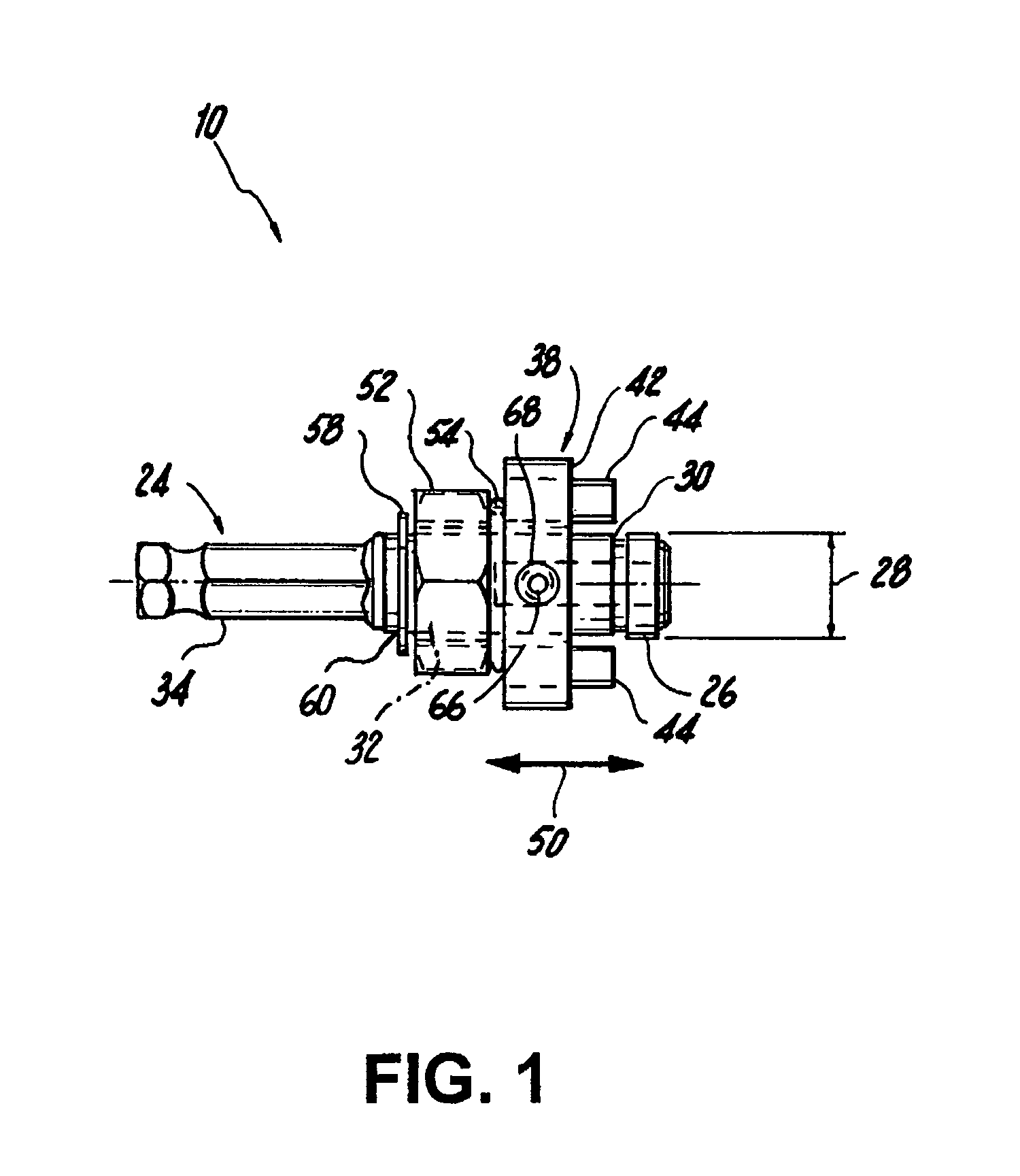
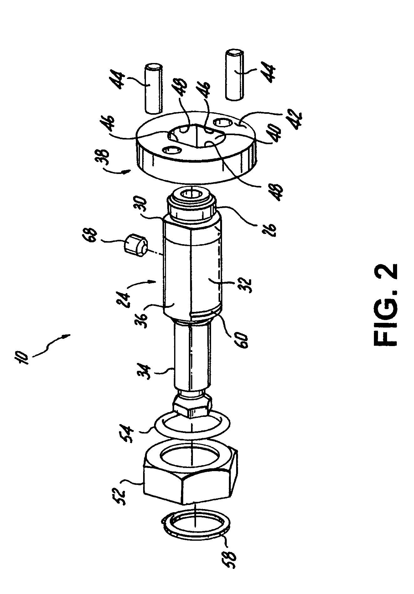
[0025]In FIGS. 1–8, an arbor embodying the present invention is indicated generally by the reference numeral 10. The arbors of the present invention are usable with hole cutters, such as hole saws and sheet metal hole cutters. The term “hole cutter” is used herein to mean any of numerous different type of cutting tools for cutting holes in work pieces, such as hole saws, sheet metal hole cutters, etc. The term “arbor” is used herein to mean any of numerous different types of devices for supporting a rotating tool, such as a hole cutter, on a power tool such as a drill, and further includes, without limitation, mandrels. In FIGS. 5–10, the illustrated hole cutters are sheet metal hole cutters of the type disclosed in co-pending U.S. utility patent application Ser. No. 10 / 869,267, entitled “SHEET METAL HOLE CUTTER”, filed on Jun. 16, 2004 in the name of William B. Korb , which is assigned to the Assignee of the present invention and is hereby expressly incorporated by reference as par...


PUM

PropertyMeasurementUnit
diameteraaaaaaaaaa
resilientaaaaaaaaaa
axial movementaaaaaaaaaa

Abstract

An arbor is provided for a hole cutter having an outer surface defining a threaded hole, and a pair of pin holes spaced radially relative to the threaded hole. The arbor has an arbor body defining a threaded end portion threadedly engageable with the threaded hole of the hole cutter, a stop surface formed adjacent to the threaded end portion and spaced radially outwardly therefrom; a drive shank located on another end portion of the arbor body; and a pair of first bearing surfaces located on opposite sides of the arbor body relative to each other and extending axially along a portion of the arbor body between the stop surface and drive shank. A pin ring has an aperture formed therethrough for slidably receiving the arbor body; a pair of drive pins; a second bearing surface that is abuttingly engageable with the hole cutter with the pins received within the corresponding pin holes of the hole cutter; and a pair of third bearing surfaces that are engageable with the first bearing surfaces of the arbor body for preventing relative rotation of the pin support member and arbor body, and are movable axially over the stop surface of the arbor body and engageable with the major diameter of the threaded end portion of the arbor body.

Description

CROSS-REFERENCE TO RELATED APPLICATION[0001]This application claims priority to U.S. Provisional Application No. 60 / 482,170 filed on Jun. 24, 2003, titled “Arbor for Hole Cutter and Related Method of Use”, and is hereby expressly incorporated by reference as part of the present disclosure.FIELD OF THE INVENTION[0002]The present invention relates to arbors and methods of using arbors, and more particularly, to arbors and methods of using arbors for hole saws and other hole cutters that prevent off axis wobble of the hole saws relative to the arbors.BACKGROUND INFORMATION[0003]A typical arbor for a hole saw or other hole cutter includes an arbor body defining a threaded end portion that is threadedly engageable within the end plate of a hole saw to fixedly secure the hole saw to the arbor. A pilot drill is receivable within the threaded end portion of the arbor body and extends through the center of the hole saw. The arbor body defines a shoulder that is axially spaced adjacent to the...

Claims


Application Information

Patent Timeline
Patent Type & Authority Patents(United States)
IPC IPC(8): B23B51/04B23B31/00B23B31/107B23B31/11
CPCB23B31/008B23B31/1076B23B51/0426B23B51/0473Y10T408/895B23B2270/54Y10T408/95B23B51/04
Inventor KORB, WILLIAM B.O'KEEFE, CHARLES M.
Owner BLACK & DECKER INC
Why Eureka
Try Eureka