
Apparatus and method for preventing one way connectivity loops in a computer network

a technology of computer network and one-way connectivity, applied in the field of switches, can solve the problems of one-way loops and insufficient methods for reliably detecting one-way connectivity loops, and achieve the effect of eliminating loop formation

Inactive Publication Date: 2006-07-11
CISCO TECH INC
View PDF14 Cites 53 Cited by
  • Summary
  • Abstract
  • Description
  • Claims
  • Application Information

AI Technical Summary

Benefits of technology

The patent describes a method for assigning ports on a switch for communication in a network. These ports are assigned by a network manager to either communicate up or down the spanning tree. This assignment is important because it determines the hierarchy of switches and prevents certain ports from being selected for transmitting data packets. The method also prevents loops caused by one-way connectivity faults. Overall, the patent provides a technical solution for ensuring efficient communication in a network.

Problems solved by technology

A longstanding problem in computer network design is the problem of one way loops.
The one way connectivity problem arises when a particular port develops a faulty receiver, or the port on the other end of a link develops a faulty transmitter.
These methods are inadequate for reliably detecting one way connectivity loops.

Method used


Image

  • Apparatus and method for preventing one way connectivity loops in a computer network
  • Apparatus and method for preventing one way connectivity loops in a computer network
  • Apparatus and method for preventing one way connectivity loops in a computer network

Examples


Embodiment Construction

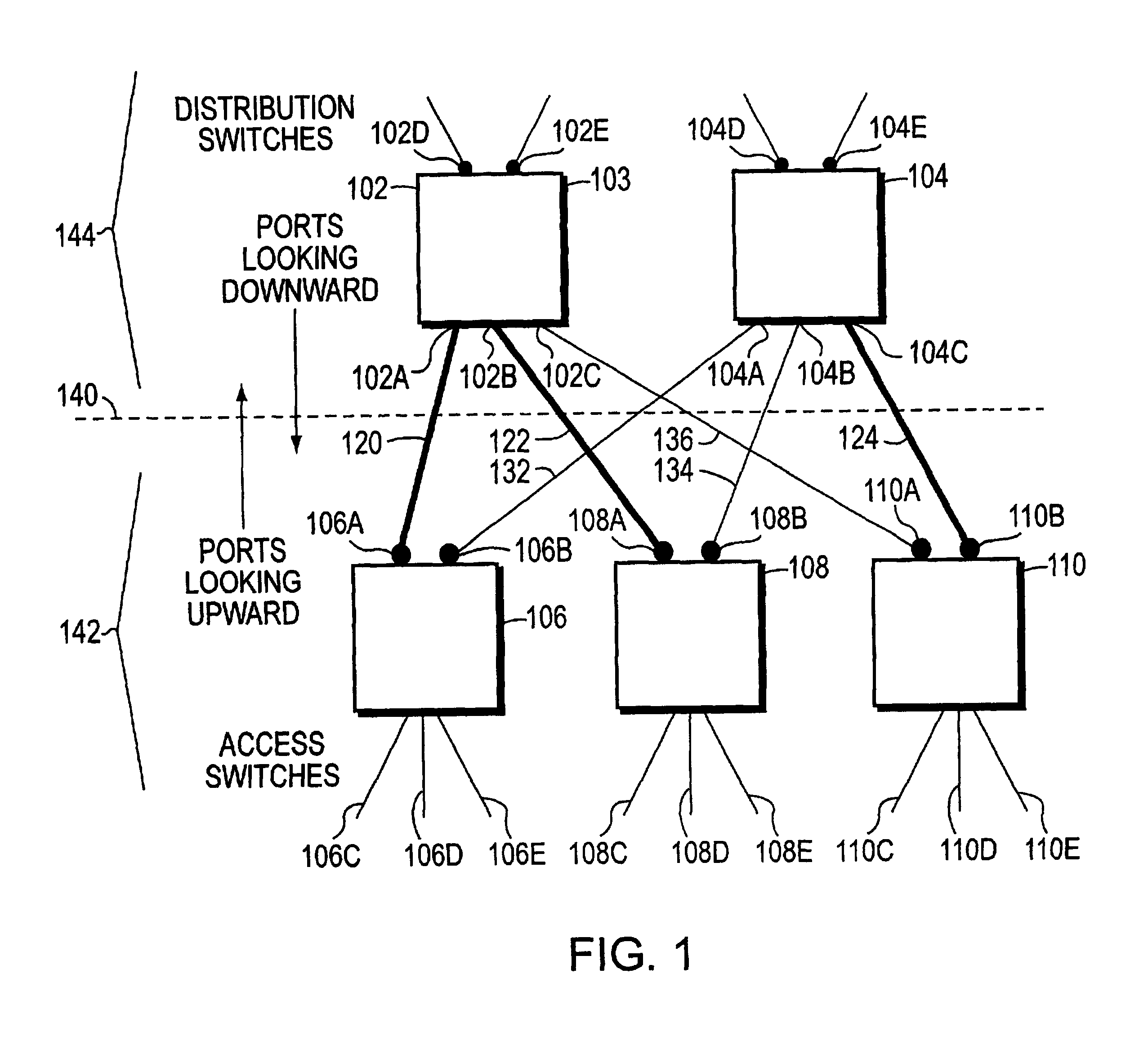
[0029]Turning now to FIG. 1, layer 2 switches 102, 104, 106, 108, and 110 are shown. Switch 102 and switch 104 represent distribution switches. Switch 106, 108, and 110 represent access switches. The access switches are selected by a person, for example a network manager, to be lower on the spanning tree than the distribution switches.

[0030]Port 106A and port 106B have Uplinkguard enabled. Switch 108 has port 108A and port 108B with Uplinkguard enabled. Switch 110 has port 110A and port 110B Uplinkguard enabled. The Uplinkguard ports of access switches 106, 108, and 110 are each connected to distribution switches 102 and 104.

[0031]For example, Uplinkguard enabled port 106A is connected to port 102A, Uplinkguard enabled port 108A is connected to port 102B. Uplinkguard enabled port 110A is connected to port 102C.

[0032]Likewise, Uplinkguard enabled port 106B is connected to port 104A. Uplinkguard enabled port 108B is connected to port 104B. Uplinkguard enabled port 110B is connected to...


PUM


Abstract

Ports of a switch are assigned by a person, for example a network manager, to be for communication up the spanning tree toward the root switch (“up ports”), or down the spanning tree away from the root switch (“down ports”). This assignment is made by enabling “Uplinkguard” status for a desired up port, and by connecting the desired port to a switch which it is desired to place in the higher layer of the spanning tree. A port having Uplinkguard enabled is prevented, for example by software or firmware in its switch, from transitioning to a designated role. Uplinkguard-enabling a port, by preventing the port from transitioning to the designated role, has at least two consequences: preventing the port from being selected by the STP to transmit to lower switches in the spanning tree; and, preventing the port from transmitting when a one way connectivity fault develops on that port. A port with Uplinkguard enabled may transition to root port role. In the event that there is one way connectivity from a port, that port will not receive BPDU messages, and if the port is in blocked state, it will believe that it should take over and become the designated port for the external link to which it is connected. Uplinkguard prevents the port from transitioning to designated role. When the port attempts to transition into designated role, Uplinkguard forces the port to transition into blocked role, thereby eliminating formation of loops caused by one way connectivity faults.

Description

BACKGROUND OF THE INVENTION[0001]1. Field of the Invention[0002]This invention relates to networks of switches operating at layer-2 and executing the spanning tree protocol.[0003]2. Background Information[0004]A longstanding problem in computer network design is the problem of one way loops. A one way loop is formed when a port develops one way communication, the port fails to receive superior BPDUs, and so transitions to designated role and begins forwarding data packets. The ports on each end of the one way link may make this transition, and the port which the fault permits to send packets to the next switch then forms the loop.[0005]The computer network is formed from layer 2 switches with redundant connections, where the redundancy is introduced in order to provide automatic switchover in the event of failure of a switch or link. The layer 2 network having redundant connections is normally prevented from having loops by use of the spanning tree protocol (STP).[0006]The STP selec...

Claims


Application Information

Patent Timeline
Patent Type & Authority Patents(United States)
IPC IPC(8): G06F1/00G06F13/00G06F13/38H04L12/56
CPCH04L45/48H04L45/00
Inventor BENEDETTO, MARCO DIMAHAJAN, UMESHGAI, SILVANO
Owner CISCO TECH INC
Learn More