Head protecting airbag device

Active Publication Date: 2006-07-18
TOYODA GOSEI CO LTD
View PDF10 Cites 30 Cited by
  • Summary
  • Abstract
  • Description
  • Claims
  • Application Information

AI Technical Summary

Benefits of technology

[0012]A first object of the invention is to provide a head protecting airbag device, in which an airbag has an inlet port for admitting inflating gas above an intermediate pillar so that the smooth expansion and inflation of the airbag can be assured even if the intermediate pillar portion is largely displaced toward the interior.
[0013]A second object of the invention is to provide an airbag, which can be smoothly inflated without receiving significant damage even if a stress is concentrated at one place during inflating.

Problems solved by technology

However, the head protecting airbag device of the aforementioned construction has the following problems when the inlet port of the airbag is arranged above the intermediate pillar portion arranged between the front pillar portion and the rear pillar portion of the vehicle.
During the actual operation of the head protecting airbag device, however, an impact may be applied to the side face of the vehicle.
In this case, the inlet port itself may close the gas discharge ports and interrupt the smooth expansion and inflation of the airbag.
In case the inflator used has a high output capacity, therefore, stress may concentrate at the inner corner portion at the time of inflating the airbag, and the airbag may be damaged.

Method used


Image

  • Head protecting airbag device
  • Head protecting airbag device
  • Head protecting airbag device

Examples


first embodiment

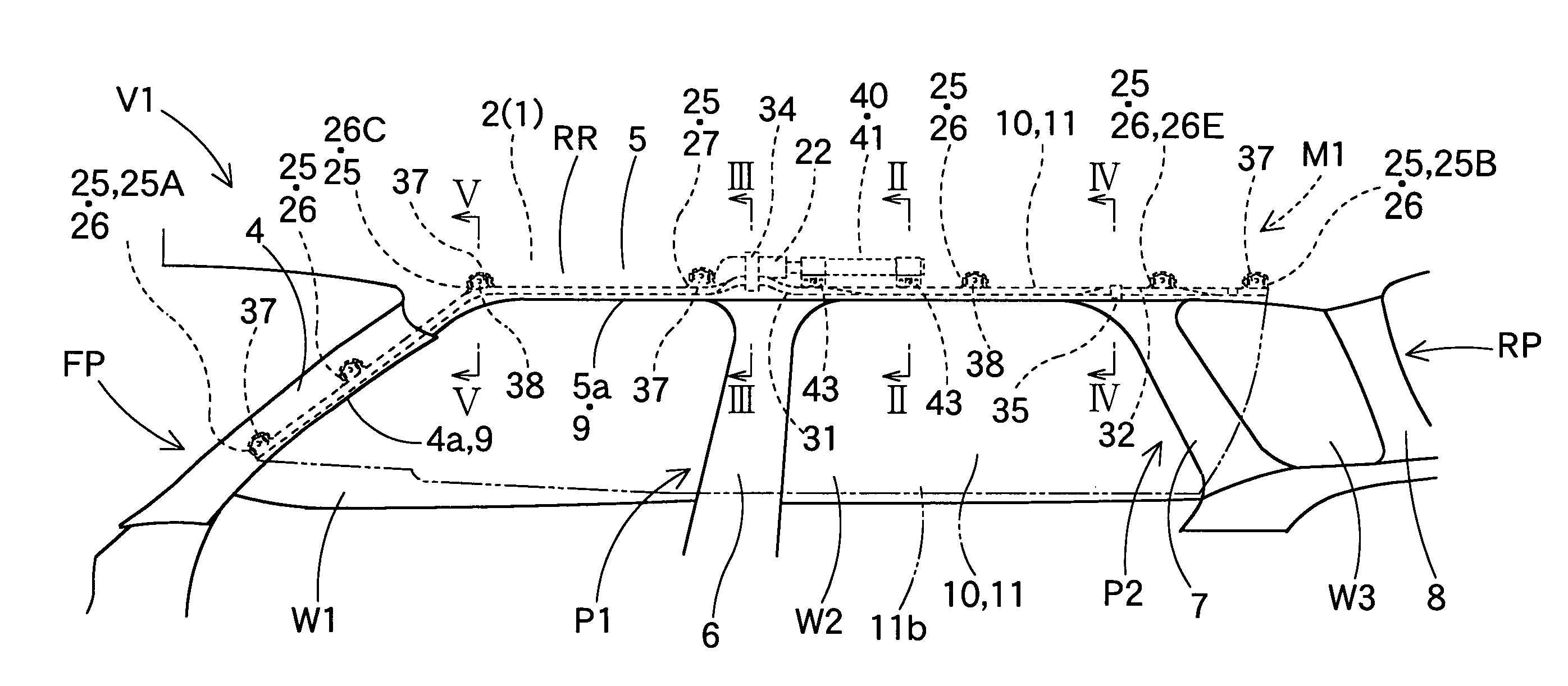
[0096]Below are described head protecting airbag devices M1 / M2, which can achieve the first object of the invention. The head protecting airbag device M1 of the first embodiment is mounted on a front pillar portion FP and a roof side rail portion RR on the upper edge of the windows (side windows) W1 / W2 / W3 of a vehicle V1, as shown in FIG. 1. Here in this vehicle V1, a first intermediate pillar portion P1 and a second intermediate pillar portion P2 are arranged between the front pillar portion FP and a rear pillar portion RP.

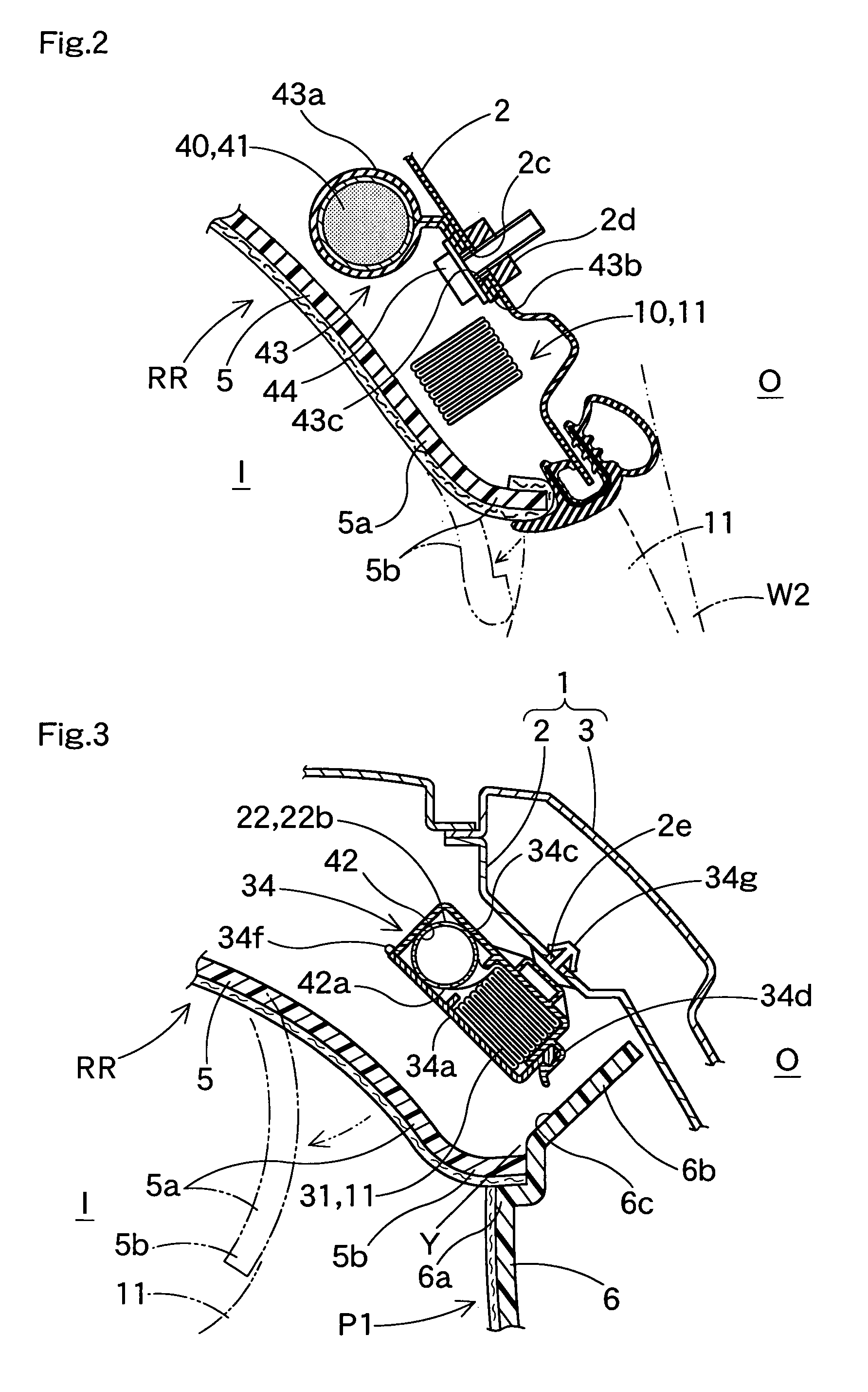
[0097]As shown in FIGS. 1 to 5, the head protecting airbag device M1 is provided with an airbag 10, clamps 34 / 35, mounting brackets 37 / 43 and a gas feeder member 40. The head protecting airbag device M1 is housed while being covered with an airbag cover 9, when it is mounted on the vehicle V1. In the case of the embodiment, the airbag cover 9 is constructed from a lid 4a on the lower edge of a front pillar garnish 4 for covering the vehicular interior side of the...

second embodiment

[0142]In a head protecting airbag device M2 of a second embodiment shown in FIG. 20, moreover, a vicinity mounting portion 27C and an inlet port 22 in an airbag 10C, and a gas feeder member 40 are offset from the center in the longitudinal direction of the vehicle V1 over the first intermediate pillar portion P1, toward the front side or the rear side of the vehicle. In the case of the embodiment, the vicinity mounting portion 27C, the inlet port 22 and the gas feeder member 40 are offset to the rear side of the top of pillar portion P1.

[0143]Here in this second embodiment, in addition to the aforementioned offset arrangement, the inlet port 22 is not arranged at the threaded portion 31, which is arranged above the pillar portion P1. Near the vicinity mounting portion 27C, therefore, there is also arranged an extension similar to that 18a of the airbag 10 of the first embodiment. The construction is further modified so that a slit 28 is not formed between the vicinity mounting porti...

third embodiment

[0147]Next will be described an airbag achieving the third object of the invention. A third embodiment will be exemplified by a head protecting airbag device.

[0148]The airbag 110 of a head protecting airbag device M3 of the third embodiment is folded and housed in the front pillar portion FP and the roof side rail portion RR on the upper edge of the windows (side windows) W4 / W5 and the rear pillar portion RP, as shown in FIG. 22. Here, this vehicle V2 is constructed by arranging a generally vertical center pillar portion CP between the front pillar portion FP and the rear pillar portion RP and by arranging a small window W6 in the region of the rear pillar portion RP. Here in the head protecting airbag device M3, the description of the members similar to those of the aforementioned airbag device M1 will be omitted, designating them by the same reference numerals.

[0149]As shown in FIGS. 22 to 25, the head protecting airbag device M3 is provided with the airbag 110, clamps 34 / 35, moun...


PUM


Abstract

A head protecting airbag device comprises an airbag and a gas feeder member. The airbag includes a main portion, an inlet port and a plurality of mounting portions. The inlet port is connected above an intermediate pillar portion to a gas feeder so as to admit inflating gas downward into a gas receiving portion of the main portion. The mounting portions are composed of a vicinity mounting portion arranged close to the inlet port, and general mounting portions. A recess is formed between the vicinity mounting portion and the inlet port. This recess substantially enlarges the length of the outer peripheral edge of the vicinity mounting portion facing the inlet port and the outer peripheral edge of the inlet port facing the vicinity mounting portion, thereby increasing the possible separation of the vicinity mounting portion and the inlet port.

Description

[0001]The present application claims priority to Japanese patent application of Inoue, filed Jun. 17, 2002, No. 2002-176154, and Japanese patent application of Inoue, filed Dec. 25, 2002, No. 2002-375109, the entirely of each is hereby incorporated into the present application by this reference.BACKGROUND OF THE INVENTION[0002]1. Field of the Invention[0003]The present invention relates to a head protecting airbag device to be mounted on a vehicle. More specifically, the invention relates to a head protecting airbag device, in which an inlet port of an airbag to be connected to a gas feeder member for feeding inflating gas is positioned above an intermediate pillar portion arranged between a front pillar portion and a rear pillar portion of the vehicle.[0004]2. Description of the Related Art[0005]A head protecting airbag device of this kind is disclosed in DE 20105734 U1. In this head protecting airbag device, an inlet port for introducing the inflating gas downward into the airbag ...

Claims


Application Information

Patent Timeline
IPC IPC(8): B60R21/16B60R21/213B60R21/232B60R21/233B60R21/235B60R21/26B60R21/261
CPCB60R21/213B60R21/232B60R21/26B60R2021/2612B60R2021/23316B60R2021/23576
Inventor INOUE, MICHIO
Owner TOYODA GOSEI CO LTD
Why Eureka
Try Eureka