
Magnetic Head Driving Piezoelectric Ceramic Actuator

Active Publication Date: 2011-04-14
MURATA MFG CO LTD
View PDF9 Cites 9 Cited by
  • Summary
  • Abstract
  • Description
  • Claims
  • Application Information

AI Technical Summary

Benefits of technology

[0011]In a specific aspect of the magnetic head driving piezoelectric ceramic actuator according to the preferred embodiments of the invention, the coating film is an insulating film. According to this configuration, for example, short circuiting between the first and second electrodes, which is caused by dust or the like, can be effectively suppressed.
[0012]In another specific aspect of the magnetic head driving piezoelectric ceramic actuator according to the preferred embodiments of the invention, one of an edge of the first external electrode portion on a fourth external electrode portion side and an edge of the fourth external electrode portion on a first external electrode portion side, is covered with the coating film. According to this configuration, for example, short circuiting between the first and second electrodes, which is caused by dust or the like, can be effectively suppressed.
[0013]In still another specific aspect of the magnetic head driving piezoelectric ceramic actuator according to the preferred embodiments of the invention, the first and second electrodes apply a voltage to the piezoelectric ceramic substrate in the height direction, so that the actuator body expands and contracts in the length direction. In other words, the actuator body expands and contracts in d31 mode. In this case, due to expansion and contraction of the magnetic head driving piezoelectric ceramic actuator, great stress is likely to be applied to the part joined to the substrate. Thus, the invention in which the magnetic head driving piezoelectric ceramic actuator can be firmly fixed, is particularly effective.
[0014]In still another specific aspect of the magnetic head driving piezoelectric ceramic actuator according to the preferred embodiments of the invention, the coating film has a first portion located on the first principal surface, and a second portion located on the second principal surface, and positions of both edges of the first portion in the length direction are different from positions of both edges of the second portion in the length direction. When the magnetic head driving piezoelectric ceramic actuator is driven, stress is likely to concentrate on the edge of the coating film which changes in thickness. Thus, for example, when the positions of the both edges of the first and second portions of the coating film in the length direction correspond to each other, stress is likely to concentrate on parts of the actuator where the both edges of the coating film are provided. On the other hand, in this configuration, the positions of the both edges of the first portion of the coating film in the length direction are different from the positions of the both edges of the second portion in the length direction. Thus, concentration of stress on a specific part of the actuator, is effectively suppressed. Therefore, the mechanical durability of the magnetic head driving piezoelectric ceramic actuator can be improved.
[0015]In still another specific aspect of the magnetic head driving piezoelectric ceramic actuator according to the preferred embodiments of the invention, the coating film has a first portion located on the first principal surface, and a second portion located on the second principal surface, and at least one of both edges of each of the first and second principal surfaces in the length direction is non-parallel to the first edge surface. In this configuration, a part where the edge of the coating film, to which relatively great stress is applied when the actuator is driven, is provided, can be dispersed in the length direction. Therefore, the mechanical durability of the magnetic head driving piezoelectric ceramic actuator can be more effectively improved.
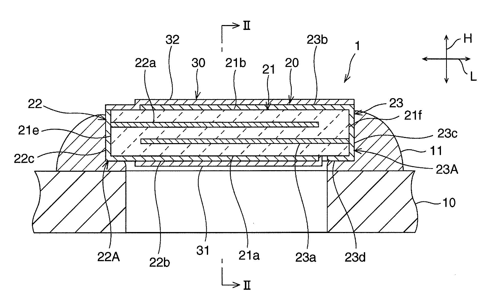
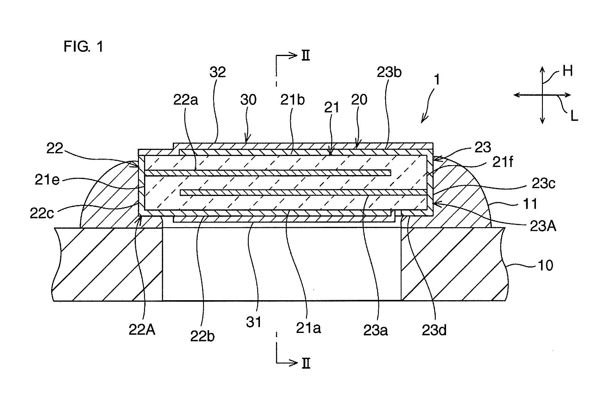
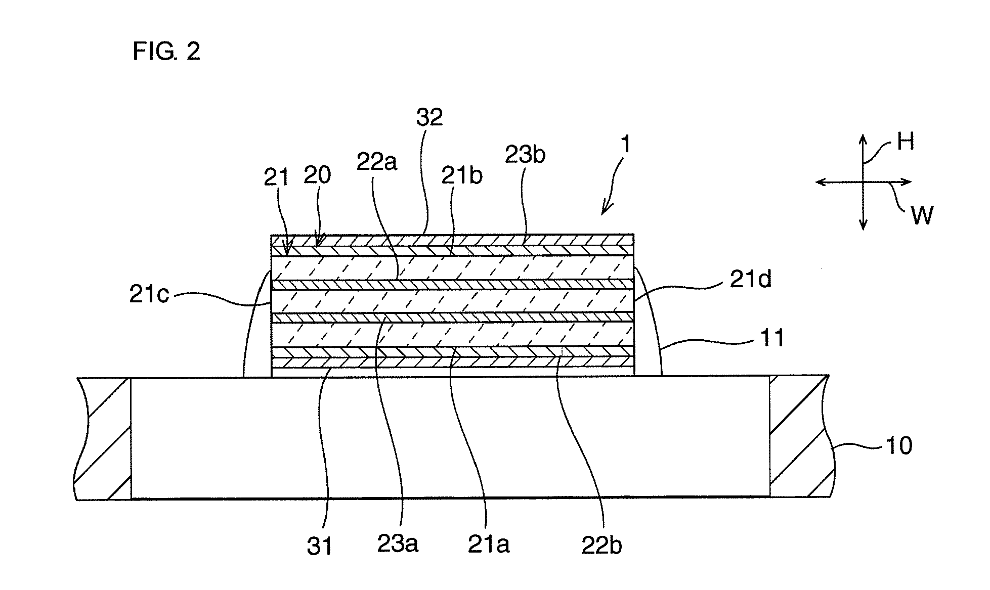
[0018]In the invention, since the coating layer is provided, generation of dust from the piezoelectric ceramic substrate when the actuator is driven, is effectively suppressed. In addition, each of the first and second electrodes is formed on the first or second edge surface and the first principal surface, and is joined to the substrate at a portion thereof which is located on the first or second edge surface, and at a portion thereof which is located on the first principal surface. Thus, the actuator is mounted on the substrate with a high mounting strength. In other words, according to the preferred embodiments of the invention, a magnetic head driving piezoelectric ceramic actuator in which dust is unlikely to be generated from a piezoelectric ceramic substrate when the actuator is driven, and which can be mounted on a substrate with a high mounting strength, can be provided.

Problems solved by technology

However, when the magnetic head is positioned by using the voice coil motor, it is difficult to sufficiently increase accuracy of positioning the magnetic head.
The piezoelectric ceramic substrate is brittle and its mechanical strength is low.
Then, if the fine dust generated from the piezoelectric ceramic substrate attaches a magnetic head or a disk, or contaminates the inside of a magnetic disk device, reliability of reading or writing information is decreased.

Method used


Image

  • Magnetic Head Driving Piezoelectric Ceramic Actuator
  • Magnetic Head Driving Piezoelectric Ceramic Actuator
  • Magnetic Head Driving Piezoelectric Ceramic Actuator

Examples


modified example

[0049]The following will describe a modified example of the above embodiment. In the following description, members having substantially the same functions as those in the above embodiment are designated by the same reference numerals, and the description thereof is omitted.

[0050]In the above embodiment, both edges of the first portion 31 of the coating film 30 in the length direction L and both edges of the second portion 32 in the length direction L are parallel to the first and second edge surfaces 21e and 21f. However, the invention is not limited to this configuration. For example, at least one of: at least one of both edges of the first portion 31 of the coating film 30 in the length direction L; and at least one of both edges of the second portion 32 in the length direction L, may be non-parallel to the first and second edge surfaces 21e and 21f.

[0051]For example, in the modified example, as shown in FIGS. 3 and 4, both edges of the second portion 32 of the coating film 30 i...


PUM


Abstract

A magnetic head driving piezoelectric ceramic actuator having an actuator body and a coating layer. The actuator body has a piezoelectric ceramic substrate and first and second electrodes. The piezoelectric ceramic substrate has first and second principal surfaces, first and second side surfaces, and first and second edge surfaces. The first electrode has a first external electrode portion formed on a part of the first principal surface, and a second external electrode portion formed on the first edge surface. The second electrode has a third external electrode portion formed on the second edge surface, and a fourth external electrode portion formed on the first principal surface. Each of: at least a part of each of the first and second external electrode portions; and at least a part of each of the third and fourth external electrode portions, constitutes a joined portion mounted on the substrate by an electrically-conductive agent. The coating film covers at least a part of a surface of a portion of the actuator body other than the joined portions.

Description

BACKGROUND OF THE INVENTION[0001]1. Field of the Invention[0002]The invention relates to a magnetic head driving piezoelectric ceramic actuator. Specifically, the invention relates to a piezoelectric ceramic actuator for finely adjusting the position of a magnetic head of a magnetic disk device.[0003]2. Description of the Related Art[0004]In the related art, in a magnetic disk device, a voice coil motor is used as an actuator for moving a magnetic head to a desired position on a disk. However, when the magnetic head is positioned by using the voice coil motor, it is difficult to sufficiently increase accuracy of positioning the magnetic head. Thus, there is a proposal of providing a fine-motion actuator between the magnetic head and a coarse-motion actuator such as a voice coil motor, for finely adjusting the position of a magnetic head. In addition, there is a proposal of using a piezoelectric ceramic actuator as a fine-motion actuator. This is because use of the piezoelectric cera...

Claims


Application Information

Patent Timeline
IPC IPC(8): H01L41/083H01L41/053
CPCG11B5/4873G11B5/4833
Inventor NAKATANI, HIROSHINISHIKAWA, MASANAGA
Owner MURATA MFG CO LTD
Learn More