
Rotor for an Asynchronous Machine

Active Publication Date: 2019-01-17
BAYERISCHE MOTOREN WERKE AG
View PDF13 Cites 3 Cited by
  • Summary
  • Abstract
  • Description
  • Claims
  • Application Information

AI Technical Summary

Benefits of technology

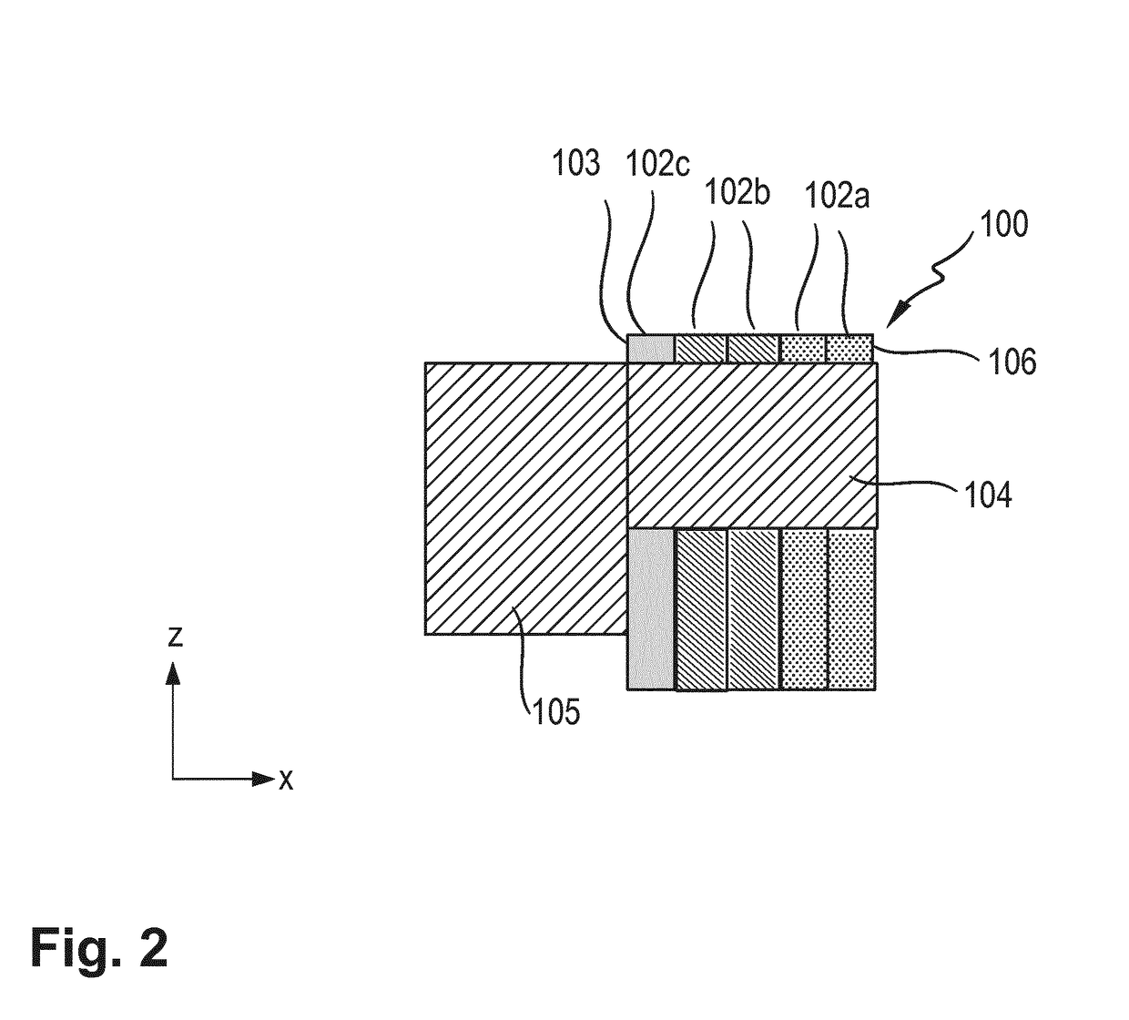
[0030]Owing to this inventive design of the laminated rotor core and, respectively, the arrangement of the at least one rotor lamination having the greater strength and/or greater rigidity in the region at the end of the laminated rotor core at which the short-circuiting ring is arranged, greater centrifugal forces and, respectively, the greater stresses which occur in the region, can be better absorbed at the webs.
[0031]As a result, the maximum possible rotation speed of the asynchronous machine which is equipped

Problems solved by technology

In said applications, there is a tendency to operate the asynchronous machines at relatively high rotation speeds with relatively low torques.
However, this is possible only to a limited extent for the following reasons.
Both the centrifugal force-dependent loading phenomena and also the temperature-related loading phenomena increase in the direction of the end sides of the laminated core and there lead to increased mechanical stresses.
The mechanical stresses which occur necessarily cause corresponding dimensioning of the webs, that is to say the region of the laminations which is located on the outside of the rods in the radial direction, and therefore limit the desirable reduction in the dimensions of the rotor and, respectively, of the asynchronous machine.
Considerations of increasing the size of the web by the cage in the laminated core

Method used


Image

  • Rotor for an Asynchronous Machine
  • Rotor for an Asynchronous Machine

Examples


Example

DETAILED DESCRIPTION OF THE DRAWINGS

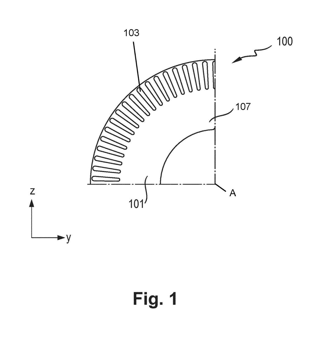
[0057]FIG. 1 shows a cross section of a rotor 100 according to the invention, wherein only one laminated rotor core 101 of the rotor 100 is shown.

[0058]The rotor 100 is formed in a rotationally symmetrical manner about a rotation axis A. The rotation axis A is perpendicular to the plane of the drawing in FIG. 1 and runs in a longitudinal direction (X-direction in FIG. 1) of the rotor 100.

[0059]In accordance with its intended use, the rotor 100 according to the invention is inserted into a stator, not shown, of an asynchronous machine and is mounted in the stator such that it can rotate about the rotation axis A.

[0060]The shown Y-direction and Z-direction correspond to the width direction and, respectively, height direction of the rotor 100 according to the invention.

[0061]The laminated rotor core 101 is constructed from a large number of rotor laminations 102 which are layered in the longitudinal direction (X-direction). Each of the rotor laminati...


PUM


Abstract

A rotor for an asynchronous machine includes a laminated rotor core which is made of a plurality of rotor laminations that are stacked in a longitudinal direction of the rotor, an intended rotational axis of the rotor running in the longitudinal direction; and a rotor cage that has a number of rotor bars, which run through the rotor laminations in the longitudinal direction, and at least one short circuit ring, which is arranged on a laminated rotor core end lying in the longitudinal direction such that the short circuit ring electrically connects the rotor bars together. The laminated rotor core contains at least one rotor lamination in a region at the end. This rotor lamination has a greater strength and/or a greater rigidity in a radial direction with respect to the rotational axis than the other rotor laminations.

Description

CROSS REFERENCE TO RELATED APPLICATIONS[0001]This application is a continuation of PCT International Application No. PCT / EP2017 / 055513, filed Mar. 9, 2017, which claims priority under 35 U.S.C. § 119 from German Patent Application No. 10 2016 204 782.5, filed Mar. 23, 2016, the entire disclosures of which are herein expressly incorporated by reference.BACKGROUND AND SUMMARY OF THE INVENTION[0002]The invention relates to a rotor for an asynchronous machine, and to an asynchronous machine having a rotor of this kind.[0003]Electrical machines, such as asynchronous machines, are used as electrical drive assemblies of motor vehicles or utility vehicles, such as, for example, electric vehicles, hybrid vehicles, etc.[0004]In said applications, there is a tendency to operate the asynchronous machines at relatively high rotation speeds with relatively low torques. In order to achieve a greater power density in this case, it is desirable to reduce the dimensions of the asynchronous machine. H...

Claims


Application Information

Patent Timeline
IPC IPC(8): H02K15/00H02K17/16
CPCH02K15/0012H02K2213/03H02K17/20H02K17/165H02K17/16
Inventor WEBER, KORBINIANDEUKE, UWEGUCCIONE, AUGUSTO
Owner BAYERISCHE MOTOREN WERKE AG
Learn More