Holding mount

a technology of mounting brackets and mounting plates, applied in the direction of springs/dampers, mechanical equipment, transportation and packaging, etc., can solve the problems of not having the required rigidity/strength, reducing the available payload of vehicles,

Active Publication Date: 2021-01-19
SAF HOLLAND GMBH
View PDF18 Cites 3 Cited by
  • Summary
  • Abstract
  • Description
  • Claims
  • Application Information

AI Technical Summary

Benefits of technology

[0007]The outer section and the inner section of the insert part are expediently connected above the shoulder, a size of the shoulder corresponding substantially to a wall thickness of the side wall or walls. The connecting section is therefore expediently connected to the side walls in a positively locking manner, as a result of which locking and pre-positioning of the insert part relative to the holding mount are made possible. The addressed locking and pre-positioning are also achieved, in particular, by virtue of the fact that the insert part has a wall thickness which is greater than a wall thickness of the side walls, a ratio of a wall thickness of the side walls to a wall thickness of the insert part lying in a range of approximately from 0.4 to 0.8, preferably in a range of approximately from 0.5 to 0.7. The relatively great wall thickness of the insert part expediently of course also contributes to a greater strength and / or rigidity of the overall holding mount.
[0010]In accordance with one preferred embodiment, the holding mount widens along the vertical axis away from the arrangement region, the reinforcing section preferably extending into the widened region. A ratio of the width of the tapered region to the width of the widened region expediently lies at approximately from 0.5 to 0.95, preferably from 0.7 to 0.9. The tapering in the direction of the arrangement region entails the advantage that material can be saved as a result. Moreover, a very rigid structure is provided and it is made possible to fasten a holding mount of this type even to very narrow (longitudinal) carriers. The fact that the reinforcing section extends as far as into the widened region entails the advantage that firstly the widened region is also reinforced and secondly precisely said transition zone is also reinforced. It has thus been shown that compressions or buckling of components can occur precisely in the region of (cross-sectional) transitions of this type. It is therefore particularly advantageous that the insert part contributes to a reinforcement of the holding mount even in said region.
[0018]The mounting opening particularly preferably has a web or collar, the holding mount or the arrangement region being arranged or fastened within the web or the collar. The mounting opening entails the advantage that the weight of the mounting plate can be reduced as a result. In addition to an optimum welding surface, the web or collar in turn entails the advantage that the mounting plate per se and, moreover, the arrangement of the holding mount relative to the mounting plate are reinforced.

Problems solved by technology

The known holding mounts entail the disadvantage that they are either very heavy, which reduces the available payload of the vehicles, or secondly do not have the required rigidity / strength.

Method used


Image

  • Holding mount
  • Holding mount

Examples


Embodiment Construction

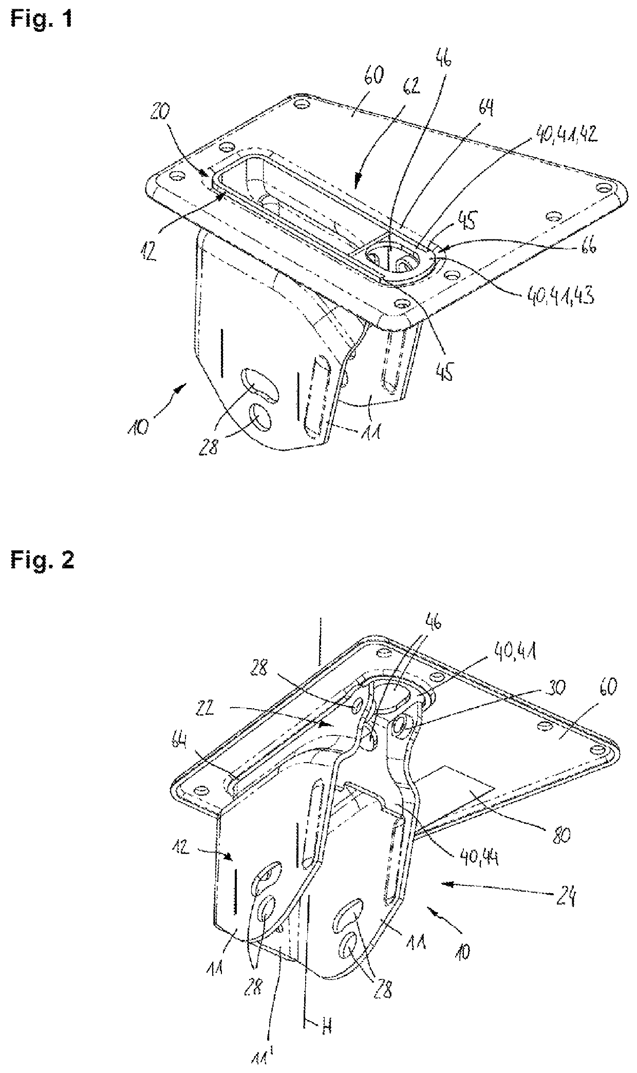
[0026]FIG. 1 shows a perspective illustration (obliquely from above) of a holding system, comprising a holding mount 10 which comprises two side walls 11, and a load-bearing element 60. The side walls 11 comprise a very wide variety of fastening openings 28 which serve, for example, to mount a longitudinal link (not shown here). The holding mount 10 is connected via an arrangement region 20 to the load-bearing element 60 which is a mounting plate 60 in the embodiment which is shown here. An insert part 40 can be seen in the region of the arrangement region 20, which insert part 40 also forms the arrangement region 20. In particular, a connecting section 41, an inner section 42 and an outer section 43 can be seen. It becomes clear, in particular, that an outer contour 12 of the side walls 11 is continued by way of the outer section 43 of the insert part 40, with the result that a circumferential gap 66 is formed in interaction with a web / collar 64 of the mounting plate 60, which circ...


PUM


Abstract

A holding mount for a commercial vehicle trailer includes two side walls which extend along a vertical axis and which form an arrangement region for arranging the holding mount on a load-bearing element, the holding mount further including an insert part which has a connecting section and a reinforcing section, the connecting section forming the arrangement region, and the reinforcing section extending between the side walls along the vertical axis for the reinforcement purposes.

Description

BACKGROUND OF THE INVENTION[0001]The present invention relates to a holding mount, in particular of or for a commercial vehicle trailer, to a holding system and to a mounting plate.[0002]Holding mounts of the type addressed here are used, in particular, to mount chassis components. To this end, the holding mounts are fastened to a load-bearing structure, for example a commercial vehicle frame, said holding mounts having openings or bearing points, in order, for example, to rotatably mount a longitudinal link and / or to arrange a spring or shock absorber element, etc. The known holding mounts entail the disadvantage that they are either very heavy, which reduces the available payload of the vehicles, or secondly do not have the required rigidity / strength.[0003]It is therefore an object of the present invention to specify a holding mount, a holding system and a mounting plate which eliminate the abovementioned disadvantages and, with a low build-up of material, make a very rigid fasten...

Claims


Application Information

Patent Timeline
Patent Type & Authority Patents(United States)
IPC IPC(8): B60G7/02B60G11/10B60G9/00
CPCB60G7/02B60G9/003B60G11/10B60G2200/31B60G2204/143B60G2206/601B60G2206/722B60G2206/8103B60G2206/8201B60G2300/04
Inventor GALAZIN, GREGORYHAMMER, EDWARD
Owner SAF HOLLAND GMBH
Why Eureka
Try Eureka