
Osseointegrative Spinal Fixation Implants

a spinal fixation and osseointegration technology, applied in the field of spinal surgery implants, can solve the problems of increasing the cost of surgery, and exposing patients to additional risks, so as to achieve the effect of short term, greater strength and rigidity of the construction

Inactive Publication Date: 2014-09-11
LITTLE KENNETH M
View PDF12 Cites 1 Cited by
  • Summary
  • Abstract
  • Description
  • Claims
  • Application Information

AI Technical Summary

Benefits of technology

The present invention is a spinal implant system that allows for better bone growth and fusion in spinal surgeries. It includes an osseointegrative bone-implant interface and a structural support that provides both short and long-term stability. The system can be used with existing posterior spinal fixation screws or a new screw with a poly-axial post. The longitudinally-extending element can be made of porous or trabecular metal or a composite design with osseointegrative materials for strength and rigidity.

Problems solved by technology

In general, relying upon implants for spinal fixation as well as graft material to achieve long-term stability (fusion) inflates the cost of surgery.
Autologous bone graft is the “gold standard” to achieve spinal fusion, but the collection and use of such materials can be painful and subject patients to additional risk for a variety of reasons.
While the use of allograft and / or bone graft substitutes may ameliorate some of those patient risks, these materials are generally thought of as not as reliable as autologous bone graft, and they can also inflate the cost of surgery as well as subject patients to additional risks.
However, a number of disadvantages are attendant with such plating systems, including that these implants are specifically designed and intended for anterior surgery (i.e., placed on the anterior faces of adjacent vertebral bodies) and the implantation of such devices typically presents a greater technical challenge to place (as compared to other surgical approach directions), can often increase the risks of surgery, and such systems often rely upon the use of additional implants for fixation.

Method used


Image

  • Osseointegrative Spinal Fixation Implants
  • Osseointegrative Spinal Fixation Implants
  • Osseointegrative Spinal Fixation Implants

Examples


Embodiment Construction

[0039]The disclosures of the various embodiments described herein are provided with sufficient specificity to meet statutory requirements, but these descriptions are not necessarily intended to limit the scope of the claims. The claimed subject matter may be embodied in a wide variety of other ways, may include different steps or elements, and may be used in conjunction with other technologies, including past, present and / or future developments. The descriptions provided herein should not be interpreted as implying any particular order or arrangement among or between various steps or elements except when the order of individual steps or arrangement of elements is explicitly described.

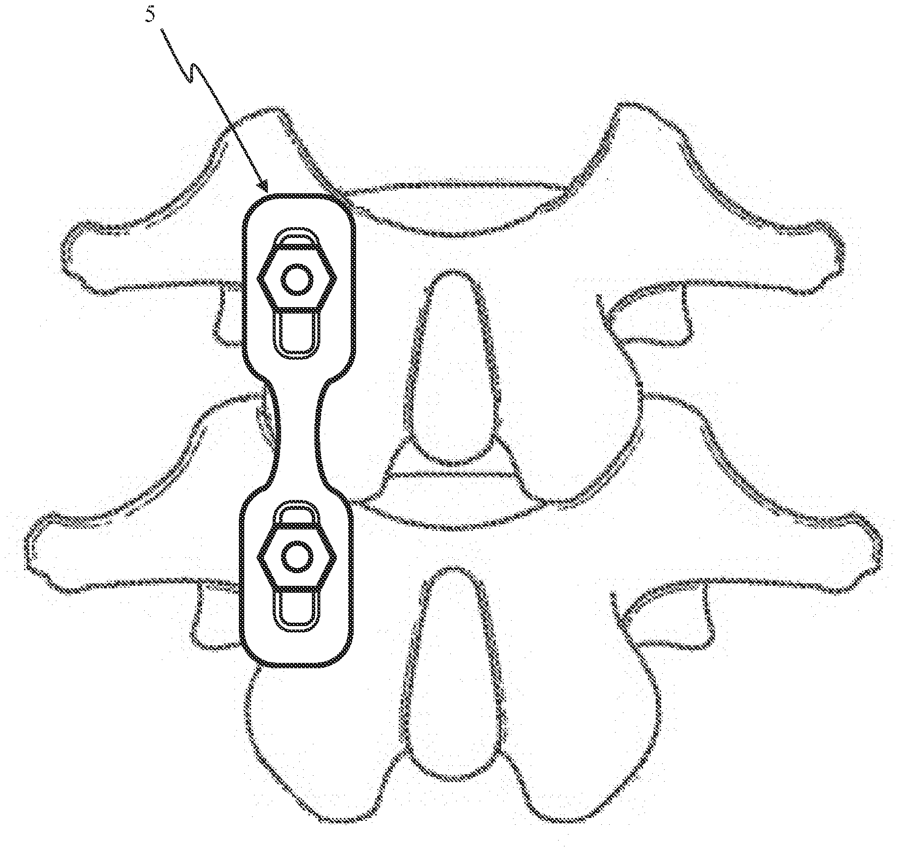
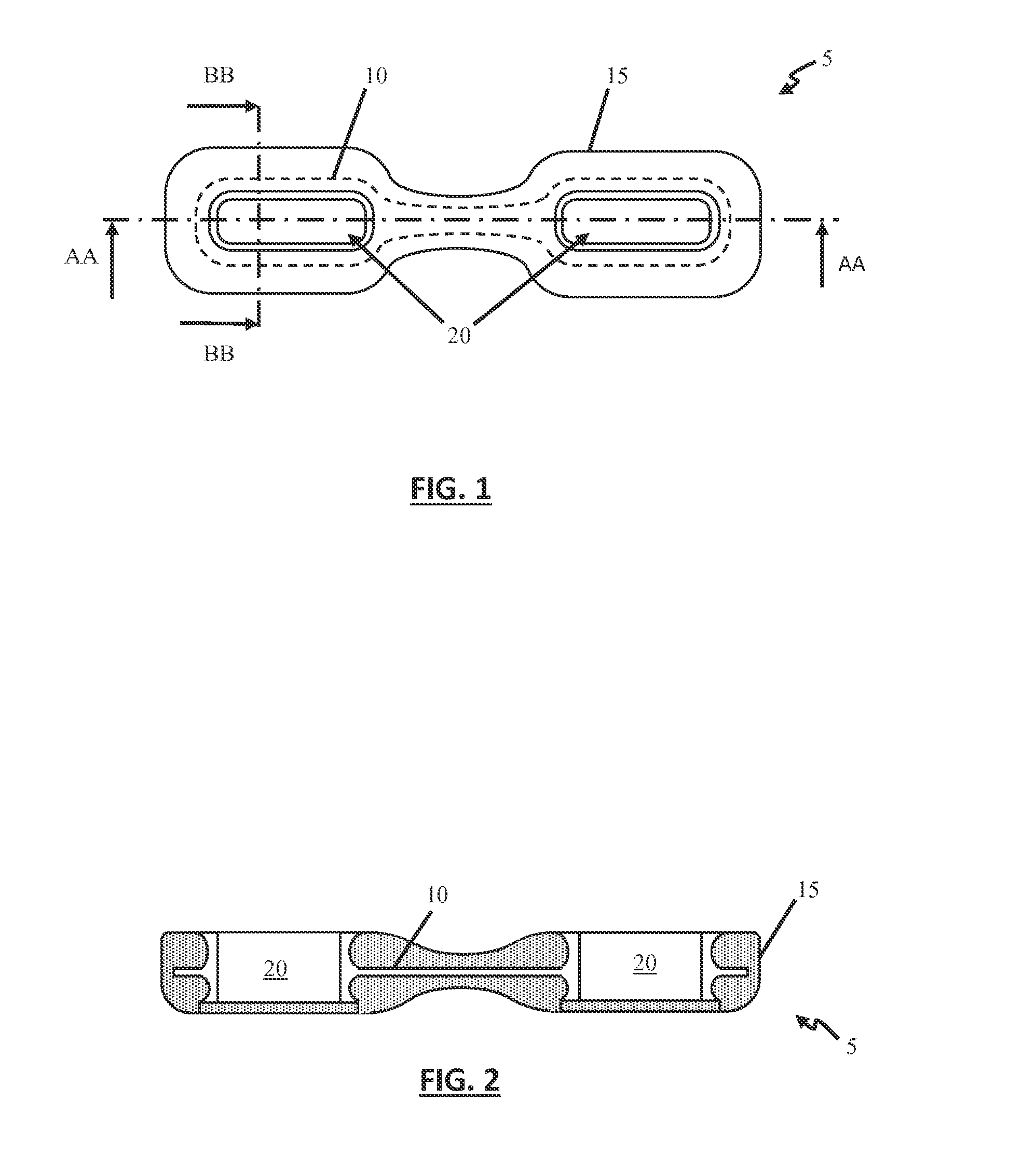
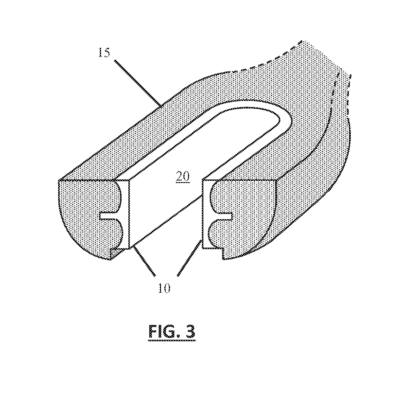
[0040]Referring now to the invention in more specific detail, FIG. 1 through FIG. 3 show one exemplary embodiment of the invention, constructed in accordance with various teachings provided herein. The device as shown is an elongated and / or semi-cylindrical plate, rod or member 5 formed as a composite s...


PUM

PropertyMeasurementUnit
widthaaaaaaaaaa
bone anchoring structureaaaaaaaaaa
strengthaaaaaaaaaa

Abstract

The present invention describes implant systems, devices, methods and surgical techniques for spinal fixation that incorporate an osseointegrative bone-implant interface that functionally provides both the short term stability of fixation and the long term stability of fusion. The various embodiments described herein can utilize novel screw and anchoring device designs or can serve as a supplement to existing spinal fixation systems.

Description

CROSS-REFERENCE TO RELATED APPLICATIONS[0001]This application claims priority from U.S. Provisional Patent Application No. 61 / 773,937, filed Mar. 7, 2013, entitled “Osseointegrative Spinal Fixation Implants” and U.S. Provisional Patent Application No. 61 / 776,375, filed Mar. 11, 2013, entitled “Osseointegrative Spinal Fixation Implants,” the contents of which are hereby incorporated herein by reference.TECHNICAL FIELD[0002]The disclosure generally relates to the field of spinal surgery implants. More particularly, the present invention discloses devices, methods, systems and surgical procedures for spine surgery, including system in the fields of posterior and posterolateral cervical, thoracic, lumbar, and sacral hardware fixation devices and natural or synthetic osseointegrative materials.BACKGROUND OF THE INVENTION[0003]Conventional methods of posterior and posterolateral cervical, thoracic, lumbar, and sacral spinal fusion surgery largely rely upon both fixation and fusion. Spinal...

Claims


Application Information

Patent Timeline
Patent Type & Authority Applications(United States)
IPC IPC(8): A61B17/70A61L27/04
CPCA61L27/04A61B17/70A61B17/7007A61B17/8605A61B17/7044A61B17/7059A61B17/7037A61L31/022A61L31/088A61L31/10A61L31/146
Inventor LITTLE, KENNETH M
Owner LITTLE KENNETH M
Learn More