
Two-piece plastic equipment pad

Active Publication Date: 2010-08-24
DIVERSITECH
View PDF35 Cites 16 Cited by
  • Summary
  • Abstract
  • Description
  • Claims
  • Application Information

AI Technical Summary

Benefits of technology

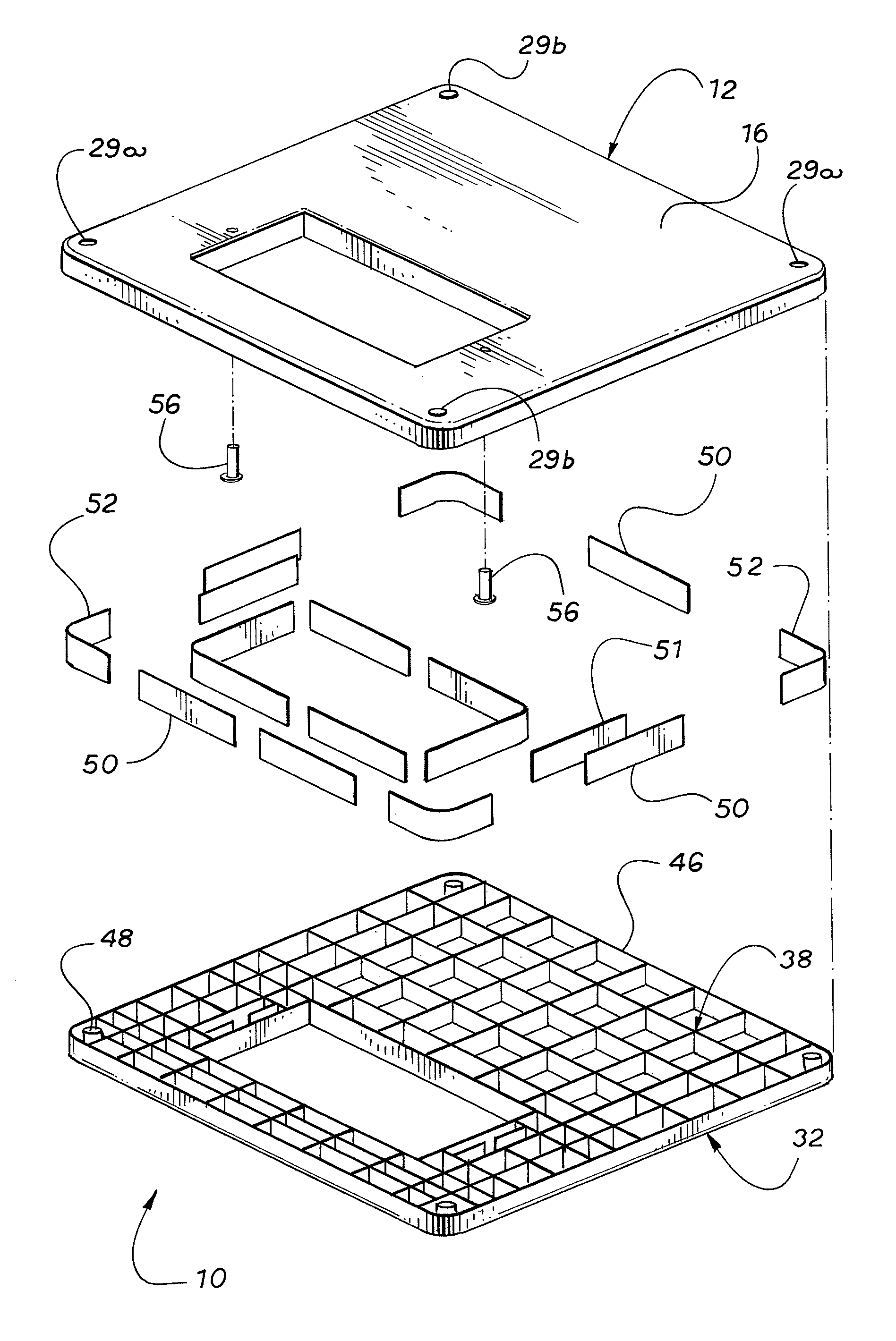
[0004]In order to overcome the drawbacks of the prior art plastic equipment pads, the present invention comprises a two-piece plastic equipment pad with a top portion and a bottom portion. The top portion and the bottom portion are mirror images of each other, and each has a base with an underlying grid structure comprising cells formed by perpendicular, crisscrossing ribs. In order to form the two-piece plastic equipment pad, the top portion and the bottom portion are aligned, grid structure to grid structure, and, in one embodiment, all are connected together by connector strips that frictionally engage support slots formed in the perpendicular ribs. In a second embodiment, the top portion and the bottom portion are connected together by plastic strips that are integrally formed in the ribs of either the top portion or the bottom portion and that engage matching slots in the ribs of the other portion. When the plastic strips are used, the top portion and the bottom portion with are welded together. The resulting equipment pad has a continuous top portion base and a continuous bottom portion base to support the equipment and to engage the ground respectively. Because the bottom portion has a continuous bottom portion base, the equipment pad has a large surface engaging the ground to provide flotation and to assure that the two-piece plastic equipment pad does not sink into the ground. Moreover, the presence of a top base portion and a bottom base portion with the interlocking support grids between the top base portion of the bottom based portion produces a structure that is substantially more rigid than a solid structure of the same mass or than the prior art structure with the open ribs on the bottom.
[0005]In the first embodiment, the connector strips are thin metal strips that include barbs for engaging the inside walls of the support slots. Consequently, the top portion and the bottom portion of the two-piece plastic equipment pad snap together without the need for tools or other instrumentalities. Alternatively, the connector strips and support slots could be replaced by cylindrical barbed rods circular support holes. Such barbed rods can be produced on nail or screw production equipment. The connector strips and support slots can be strategically positioned within the grid structure of the top portion and the bottom portion to reinforce the resulting two-piece plastic equipment pad in areas that experience greater loading and stresses such as around the periphery of the equipment pad. The second embodiment, the connector strips are plastic and serve to align the grids of the top portion and the bottom portion and to provide surfaces for welding of the top portion to the bottom portion.

Problems solved by technology

When such an equipment pad with exposed vertical ribs is placed on the ground, the ribs provided very little flotation, and the plastic transformer pad tends to sink into the ground.
Further, without a horizontal base attached to the ribs on the back of the equipment pad, the equipment pad lacks rigidity.

Method used


Image

  • Two-piece plastic equipment pad
  • Two-piece plastic equipment pad
  • Two-piece plastic equipment pad

Examples


Embodiment Construction

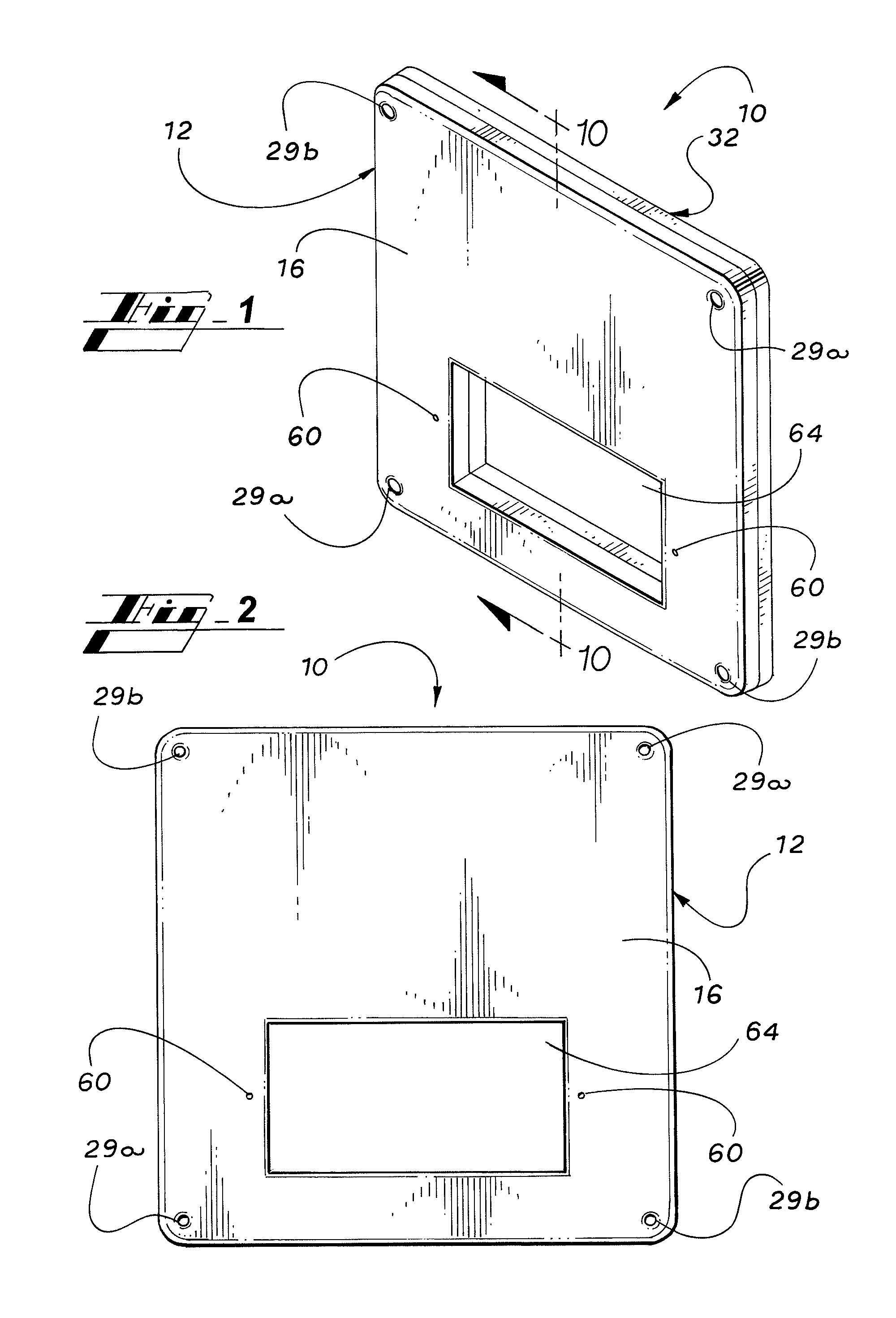
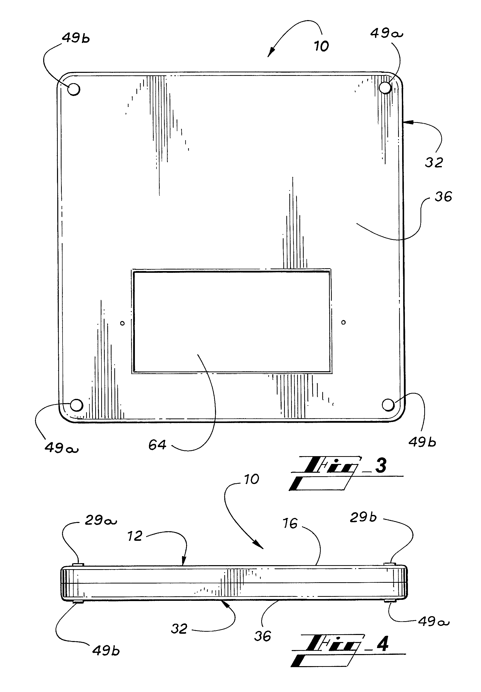
[0025]Turning to FIG. 1, a two-piece plastic equipment pad 10 is shown. The two-piece plastic equipment pad 10 is, by way of example, a transformer pad with a cable access opening 64. The access opening 64 allows access to underground electrical cables. The two-piece plastic equipment pad 10 comprises a top portion 12 and a mirror image bottom portion 32. The top portion 12 and the bottom portion 32 are both molded from any common injection moldable, thermoformed or thermoset materials, filled or unfilled. The materials may also include materials that can be welded together to form the complete pad from the top portion 12 in the bottom portion 32. Suitable materials for the top portion 12 and the bottom portion 32 of the two-piece plastic equipment pad 10 include without limitation polypropylene, Acrylonitrile Butadiene Styrene (ABS), and styrene. Other methods besides molding may be used to produce the top portion 12 and the bottom portion 32 of the two-piece plastic equipment pad ...


PUM


Abstract

A two-piece plastic equipment pad with a top portion and an identical bottom portion. Each portion has a base with an underlying grid structure comprising cells formed by perpendicular ribs. The top portion and the bottom portion are aligned and connected together by connector strips that slots formed in the perpendicular ribs of the grid structure of the top portion and the bottom portion.

Description

CROSS REFERENCE TO RELATED PATENT APPLICATIONS[0001]This patent application claims priority from U.S. Provisional Patent Application No. 61 / 028,621, filed Feb. 14, 2008, which is hereby incorporated by reference.FIELD OF THE INVENTION[0002]This invention relates to equipment pads for supporting large pieces of equipment, such as HVAC compressors, electrical transformers, or the like on the ground.BACKGROUND OF THE INVENTION[0003]Traditionally, equipment pads were concrete slabs poured in place to support large pieces of equipment. Subsequently, lightweight concrete pads were pre-cast and delivered to the location for supporting the equipment. In order to save weight and cost, plastic equipment pads were developed to support the equipment. A typical plastic transformer equipment pad is disclosed in Schlegel U.S. Pat. No. 6,186,468. The transformer equipment pad disclosed in the Schlegel patent comprises a top base on which the transformer is positioned and an underlying cellular stru...

Claims


Application Information

Patent Timeline
IPC IPC(8): F16M3/00
CPCE02D27/44
Inventor WARD, CHARLES BARRYBERTOLI, KENNETHPLATT, KEITH
Owner DIVERSITECH
Learn More