This helps you quickly interpret patents by identifying the three key elements:
Problems solved by technology
Method used
Benefits of technology
[0008]After long-term investigation, the inventor proposes that an easy way to overcome the squirting problem is to configure stress concentrators at an appropriate location of a lubricant pack. According to continuum mechanics, a stress means force endured on unit area. In other words, the smaller the unit area is, the greater the stress is. Thereby, the stress concentrators are ready to be breakdown points. Such theory is a
Problems solved by technology
During cutting, friction of the metallic cutting blades results in high temperature.
After long-term use, the efficiency of the cutting blades reduces, and the noise generated by the cutting blades increases, so that entire operating life of the paper shredder lowers.
However, when the lubricant pack passes through cutting blades
Method used
Image
Click on the blue label to locate the original text in one second.
Reading with bidirectional positioning of images and text.
Examples
Example
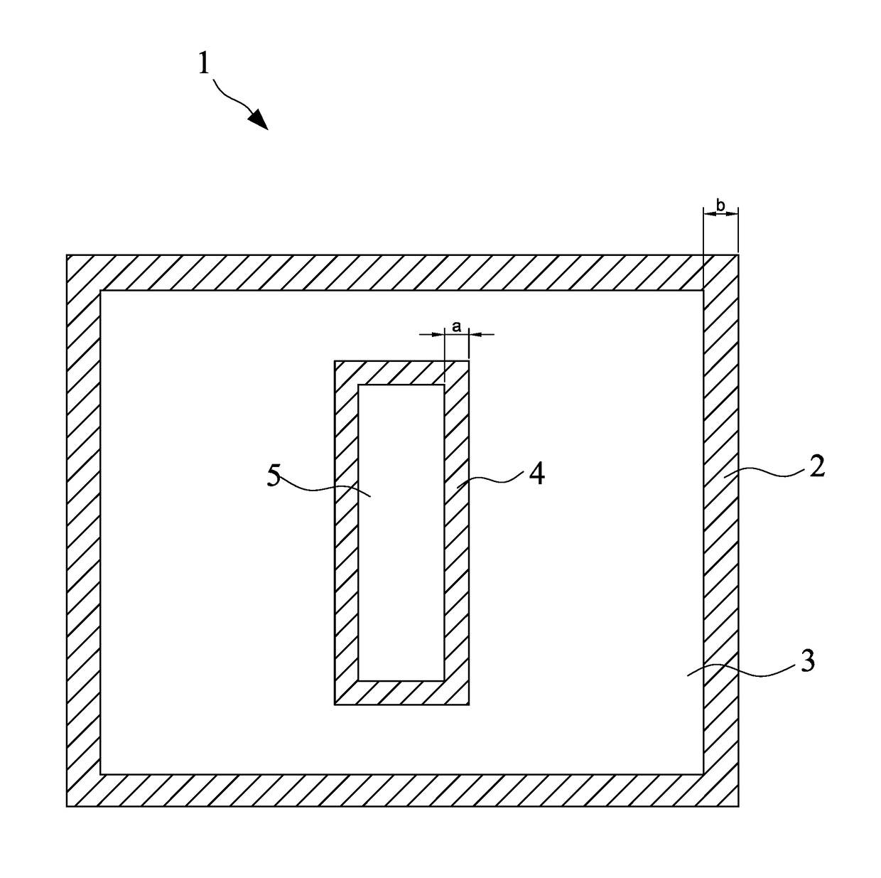
[0018]As shown in FIG. 1, a lubricant pack (1) according to a first embodiment of the present invention is depicted, which includes two covering layers disposed side-by-side and edges (2) thereof are thermally welded to form a sealed bag (3). Lubricant (not shown) is enclosed within the bag (3). The characteristic of the present embodiment is that at least one inner seal (4) is configured in the bag (3), and surrounded by the inner seal (4) is a hollow region (5) not containing the lubricant. Preferably, a width (a) for sealing the hollow region is smaller than that (b) for sealing the bag. As such, when a paper shredder cuts the lubricant pack, the smaller width forms stress concentrates to release air contained in the lubricant from the hollow region (5).
[0019]In this embodiment, the hollow region (5) may be in a lengthwise rectangle, but may be in another geometrical shape, e.g. a circular shape, a star shape, or a polygonal shape.
Example
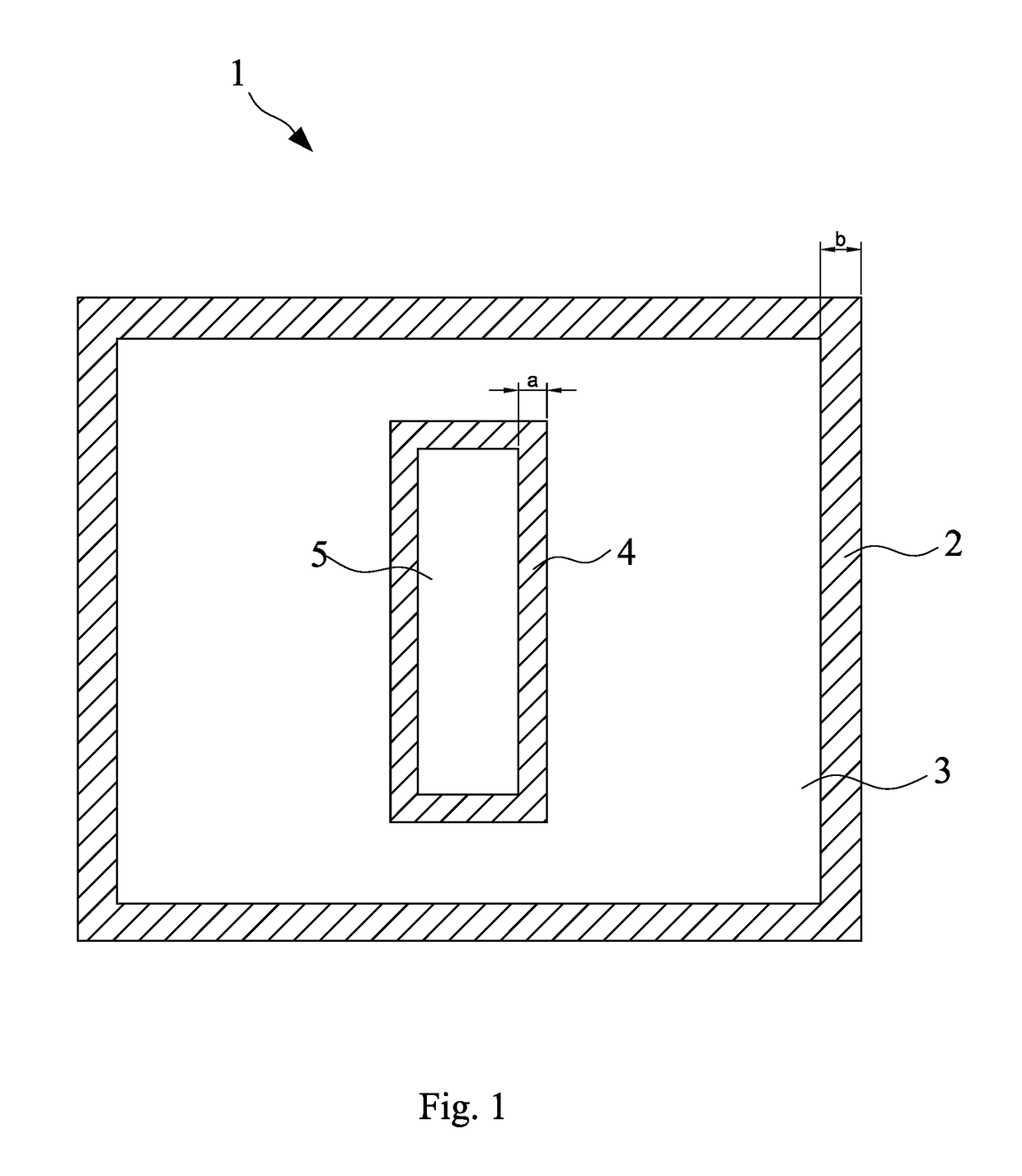
[0020]As shown in FIG. 2, multiple hollow regions (5) according to a second embodiment are arranged in parallel laterally.
Example
[0021]As shown in FIG. 3, a hollow region (5) according to a third embodiment is in a cruciform formed with a lengthwise hollow region and a widthwise hollow region.
[0022]As shown in FIG. 4, a hollow region in a lengthwise rectangle is further sealed to separate to multiple small hollow regions (51, 52, 53, and 54).
[0023]As shown in FIG. 5, since the cruciform of the hollow region (5) in the third embodiment leads to softening the lubricant pack (1), a solid reinforcing seal (41) is configured at a position where the lengthwise hollow region is intersected with the widthwise hollow region to strengthen the lubricant pack. The hollow region is separated into multiple small hollow regions (51, 52, 53, and 54) around the solid reinforcing seal (41).
[0024]Every bag (3) of the foregoing embodiments is configured with at least one inner seal (4), and surrounded by the inner seal (4) is the hollow region (5). As such, when a paper shredder cuts the lubricant pack, stress concentrators are ...
PUM
Property
Measurement
Unit
Shape
aaaaa
aaaaa
Width
aaaaa
aaaaa
Abstract
A lubricant pack for a paper shredder is presented, which includes two covering layers disposed side-by-side and edges thereof are thermally welded to form a sealed bag. Lubricant is enclosed in the bag, and at least one inner seal is configured in the bag. Surrounded by the inner seal is a hollow region not containing the lubricant. When the paper shredder cuts the lubricant pack, air contained in the lubricant tends to be released from the hollow region. Another lubricant pack for a paper shredder is presented, which includes two covering layers disposed side-by-side and edges thereof are thermally welded to form a sealed bag. Lubricant is enclosed in the bag, and at least one an inner seal is configured in the bag. Surrounded by the inner seal is a solid region not containing the lubricant, and multiple hollow impressions are formed in the solid region. When the paper shredder cuts the lubricant pack, air contained in the lubricant tends to be released from the hollow impressions of the solid region.
Description
FIELD OF THE INVENTION[0001]The present invention is related to a paper shredder, and more particularly to a lubricant pack for a paper shredder, wherein the lubricant can be contacted with cutting blades for the purpose of lubrication during the breaking of the lubricant pack in the paper shredder.BACKGROUND OF THE INVENTION[0002]As we know, when a paper shredder works, multiple cutting blades inserted through two parallel rotary shafts cut passing papers into pieces or chips by rotation of the rotary shafts powered by a motor and a gear box. During cutting, friction of the metallic cutting blades results in high temperature. After long-term use, the efficiency of the cutting blades reduces, and the noise generated by the cutting blades increases, so that entire operating life of the paper shredder lowers. Indeed, there is a need to maintain and lubricate the cutting blades of the paper shredder.[0003]In the first generation lubricant pack, a lubricant-soaked paper is sandwiched in...
Claims
Application Information
Patent Timeline
Application Date:The date an application was filed.
Publication Date:The date a patent or application was officially published.
First Publication Date:The earliest publication date of a patent with the same application number.
Issue Date:Publication date of the patent grant document.
PCT Entry Date:The Entry date of PCT National Phase.
Estimated Expiry Date:The statutory expiry date of a patent right according to the Patent Law, and it is the longest term of protection that the patent right can achieve without the termination of the patent right due to other reasons(Term extension factor has been taken into account ).
Invalid Date:Actual expiry date is based on effective date or publication date of legal transaction data of invalid patent.