
car seat

A technology for vehicle seats and seats, which is applied to vehicle seats, seat frames, vehicle parts, etc., can solve the problems of flange deformation and the inability of load to be effectively carried.

Active Publication Date: 2016-01-20
TS TECH CO LTD
View PDF7 Cites 0 Cited by
  • Summary
  • Abstract
  • Description
  • Claims
  • Application Information

AI Technical Summary

Problems solved by technology

[0013] In addition, with the technology disclosed in Patent Document 2, depending on the direction of the source of the load, the flange (force receiving member) may be deformed due to the influence of the load
Therefore, there is a risk that loads from other components cannot be effectively carried

Method used


Image

  • car seat
  • car seat
  • car seat

Examples


Embodiment Construction

[0068] Next, a specific implementation manner (first embodiment) of the present invention will be described in detail with reference to the accompanying drawings.

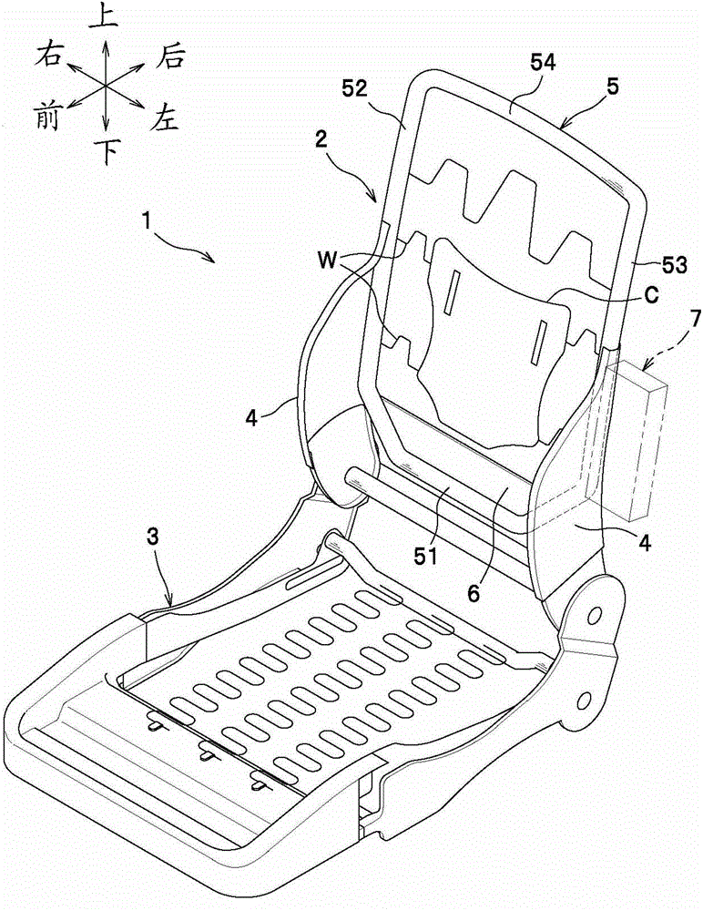
[0069] According to the present embodiment, the vehicle seat is composed of such as figure 1 The shown seat frame 1 is formed of a seat frame 1 covered on the outside with a seat cushion made of polyurethane foam or similar material. The seat frame 1 includes a seat back frame 2 and a seat bottom frame 3 . It is not difficult to understand that in the description of the present invention, the front / rear, left / right and up / down directions are stipulated as taking the view angle of the occupant sitting on the seat as the criterion.

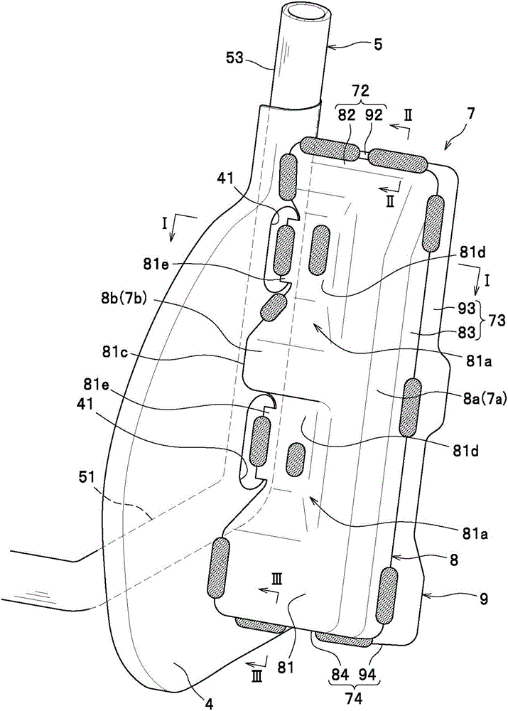
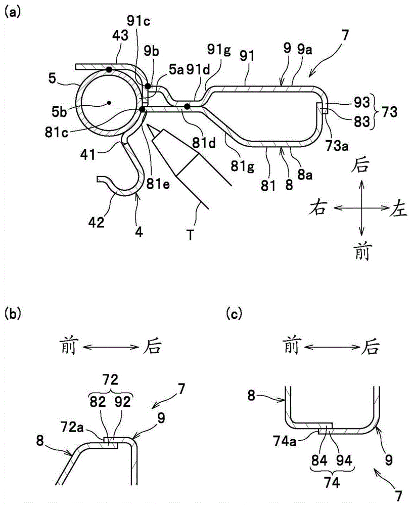
[0070] The seat back frame 2 includes a pair of side frames 4 , a pipe frame 5 as an example of a reinforcing frame (inner frame) for reinforcing the side frames 4 , a bottom frame 6 , and a bracket 7 as an example of a force receiving member.

[0071] The side frame 4 is a plate-like ...


PUM


Abstract

A vehicle seat, comprising: left and right side frames (4) constituting left and right parts of a seat back frame (2); used to strengthen the side frame (4); and a force-bearing part (bracket 7) arranged adjacent to the side frame (4), which is provided separately from the reinforcement frame and used to bear the load from other parts; wherein, The force receiving part is arranged opposite to the reinforcing frame, the side frame (4) is arranged between the force receiving part and the reinforcing frame, and the force receiving part is directly fixed on the reinforcing frame.

Description

technical field [0001] The present invention relates to a vehicle seat provided with a force-receiving part for bearing the load applied by other parts of the vehicle. Background technique [0002] So far, the vehicle seat known in the prior art (see Patent Document 1) includes a rectangular ring-shaped pipe frame (reinforcement frame), a plate-shaped side frame provided adjacent to the left or right outer side of the pipe frame, and a left side frame fixed to the side frame. Bracket (force receiving part) on the outside or right outside. Specifically, the side frame is formed with a size protruding forward and backward from the pipe frame, and the bracket is arranged at a position on the outer surface of the side frame. Like this, viewed from the side, the support covers the front half of the pipe frame and protrudes forward from the pipe frame. [0003] According to this technique, the frame is shaped like a box with front, rear, upper and lower flat sides, through which...

Claims


Application Information

Patent Timeline
Patent Type & Authority Patents(China)
IPC IPC(8): B60N2/42B60R21/02
CPCB60N2/4235B60N2/4249B60N2/68B60N2/682B60N2/42709
Inventor 郭裕之
Owner TS TECH CO LTD
Learn More