Vehicle seat

一种车辆座椅、座椅的技术,应用在车辆座椅、座椅架、车辆部件等方向,能够解决无法充分传递负载等问题

Inactive Publication Date: 2013-03-27
TS TECH CO LTD +1
View PDF7 Cites 0 Cited by
  • Summary
  • Abstract
  • Description
  • Claims
  • Application Information

AI Technical Summary

Problems solved by technology

[0004] For the above-mentioned known technology, the flange provided on the reinforcing member can bear the load on a large area, but this bearing depends on the direction of the load, and the flange may be deformed due to the influence of the load, There is therefore a risk of not being able to adequately transfer the load

Method used


Image

  • Vehicle seat
  • Vehicle seat
  • Vehicle seat

Examples


Embodiment Construction

[0021] Hereinafter, specific embodiments of the present invention will be described in detail in conjunction with the accompanying drawings.

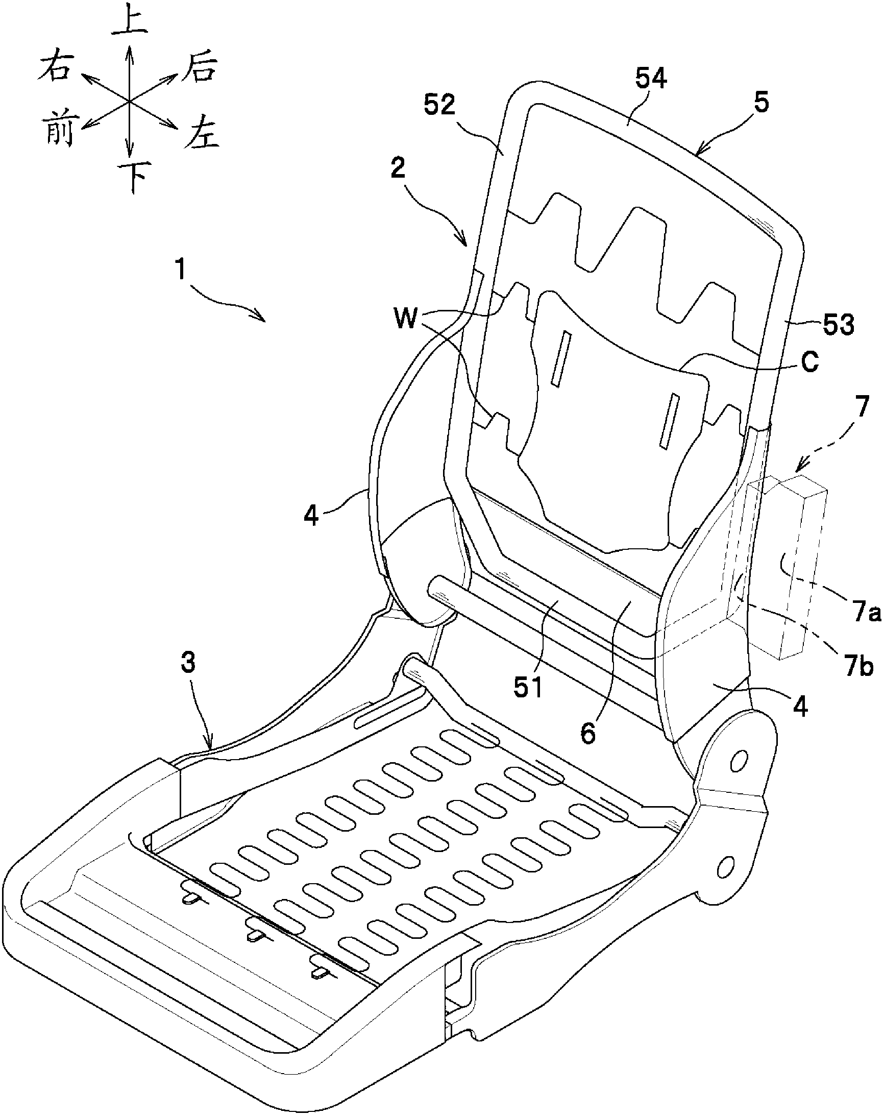
[0022] According to the present invention, the vehicle seat is composed of such as figure 1 The shown seat frame 1 is formed of a seat frame 1 covered on the outside with a seat cushion made of polyurethane foam or similar material. The seat frame 1 includes a seat back frame 2 and a seat bottom frame 3 . It is not difficult to understand that in the description of the present invention, the front / rear, left / right and up / down directions are stipulated as taking the view angle of the occupant sitting on the seat as the criterion.

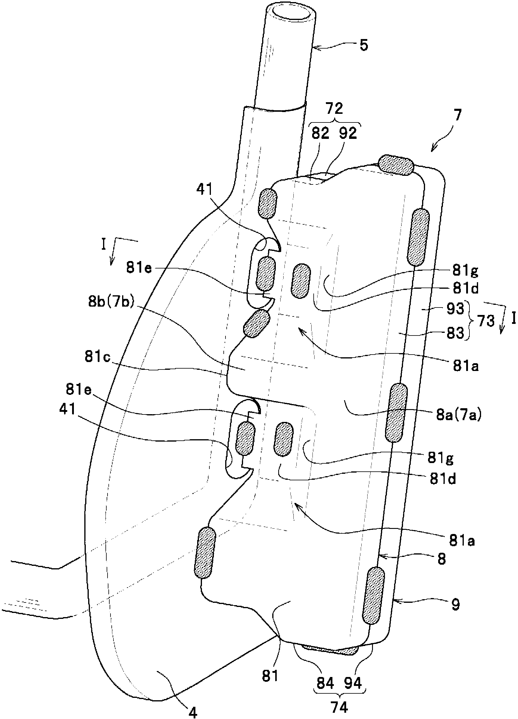
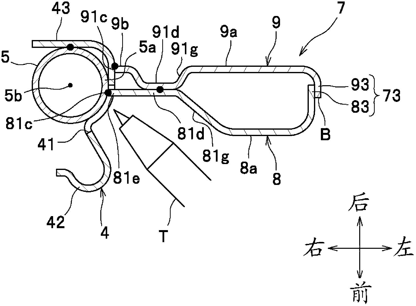
[0023] The seat back frame 2 includes a pair of side frames 4 , a pipe frame 5 as a reinforcing frame for reinforcing the side frames 4 , a bottom frame 6 , and a bracket 7 as an example of a force receiving member.

[0024] The shape of the pipe frame 5 is a cylindrical pipe (with a closed section) bent int...


PUM


Abstract

A vehicle seat is provided with: a left and right base frame (side sections (52, 53) of pipe frame (5)) forming the left and right parts of a seat back frame (2); an input member (bracket (7)) which is provided adjacent to the left or right outer side of one side (side section (53)) of the base frame, and to which external lateral load is input; and a load transfer section (lower frame (6) and lower section (51) of pipe frame (5)) for transferring the load from the input member to the side laterally opposite to the side on which the input member is provided. Furthermore, the input member has a closed cross-sectional shape, and an input side edge section (7a) has a larger diameter than an output side edge section (7b) in at least one among an upward, downward, forward and backward direction.

Description

technical field [0001] The invention relates to a vehicle seat on which a side impact load applied to a vehicle can be transmitted laterally from the outside to the inside. Background technique [0002] So far, known vehicle seats in the prior art (referring to Japanese patent document JP11-222088A) include: a seat back frame made of a rectangular frame-like tube, fixed on a The reinforcement at the position where the lateral inner lower end of the seat back frame is inclined. The reinforcement has an outer end protruding from the seat back frame and a terminal end portion provided with a flange. [0003] In such a vehicle seat, a side impact load applied to a certain flange from the laterally outer side is transmitted to the side laterally opposite to the side on which the flange is located through the reinforcement and the other flange. [0004] For the above-mentioned known technology, the flange provided on the reinforcing member can bear the load on a large area, but ...

Claims


Application Information

Patent Timeline
Patent Type & Authority Applications(China)
IPC IPC(8): B60N2/42B60R21/02
CPCB60N2/42709B60N2/4235B60R21/02B60N2/42B60N2/68B60N2/682B60N2/4249
Inventor 郭裕之山木状元奥尚人
Owner TS TECH CO LTD
Why Eureka
Try Eureka