
Method of and apparatus for multi-channel management, multi-channel interference management method, multi-channel terminal, method of and apparatus for multi-channel setting, and computer product

Inactive Publication Date: 2006-07-18
FUJITSU LTD
View PDF11 Cites 34 Cited by
  • Summary
  • Abstract
  • Description
  • Claims
  • Application Information

AI Technical Summary

Benefits of technology

[0033]It is an object of the present invention to provide a method of and an apparatus for multi-channel management, a multi-channel interference management method, a multi-channel terminal, a method of and an apparatus for multi-channel setting, and a computer product that can prevent interference in multi-channel communications and that can carry out a channel setting quickly and accurately.

Problems solved by technology

Therefore, users cannot easily understand channels that have been set at other terminals and radio keyboards.
In this case, there has been a problem that the terminal 101 can receive key data from both the radio keyboard 201 and the radio keyboard 202, and this results in the occurrence of interference.
Further, there has been a problem that even if the set channel of the terminal 101 and the radio keyboard 201 has been changed from the channel CH1 to the channel CH2, the terminal 101 can receive the key data from both the radio keyboard 201 and the radio keyboard 202, and this results in the occurrence of interference.
As a result, there has been a problem that it takes time to set the channels, and errors easily occur in the channel setting.

Method used


Image

  • Method of and apparatus for multi-channel management, multi-channel interference management method, multi-channel terminal, method of and apparatus for multi-channel setting, and computer product
  • Method of and apparatus for multi-channel management, multi-channel interference management method, multi-channel terminal, method of and apparatus for multi-channel setting, and computer product
  • Method of and apparatus for multi-channel management, multi-channel interference management method, multi-channel terminal, method of and apparatus for multi-channel setting, and computer product

Examples


first embodiment

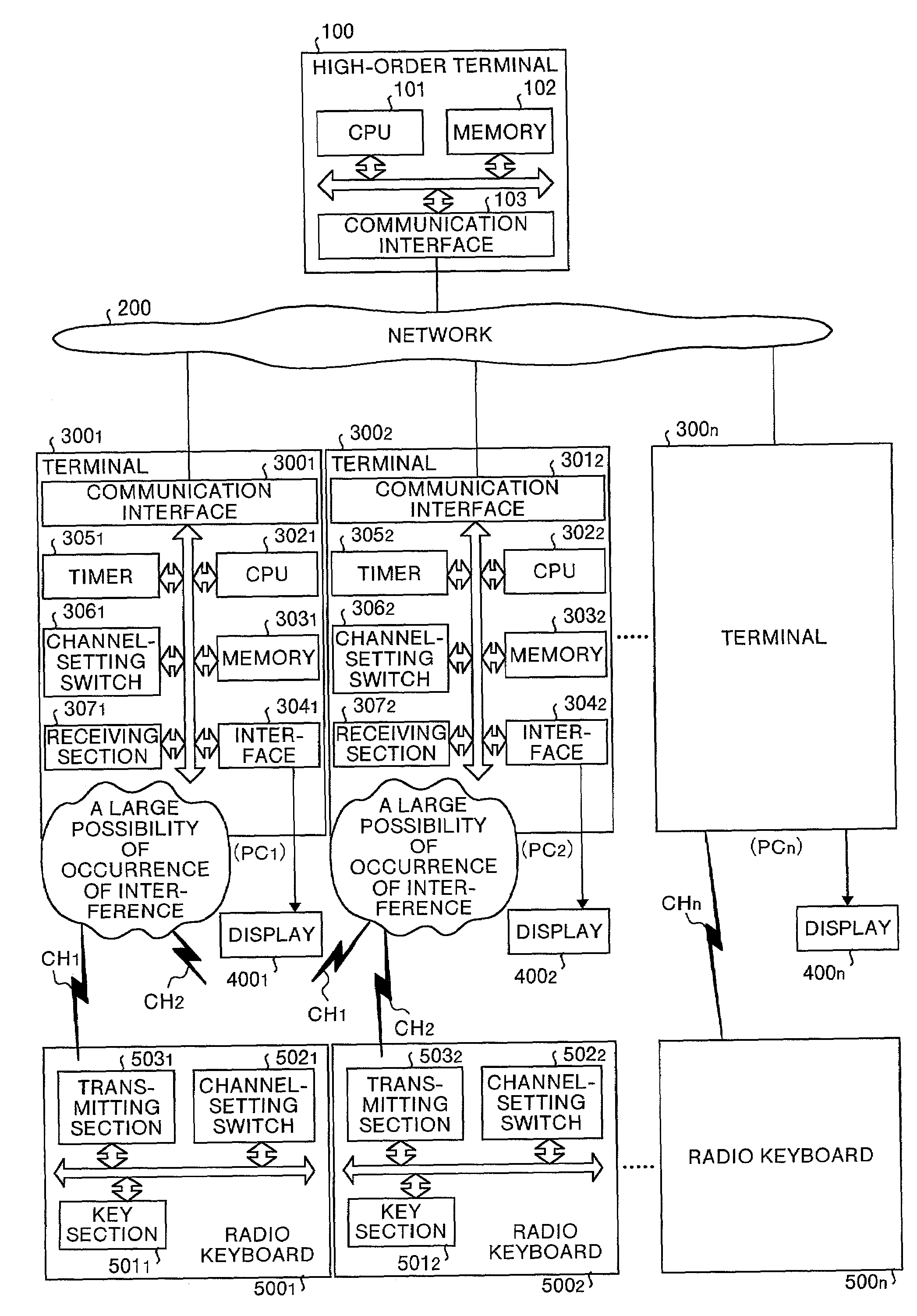
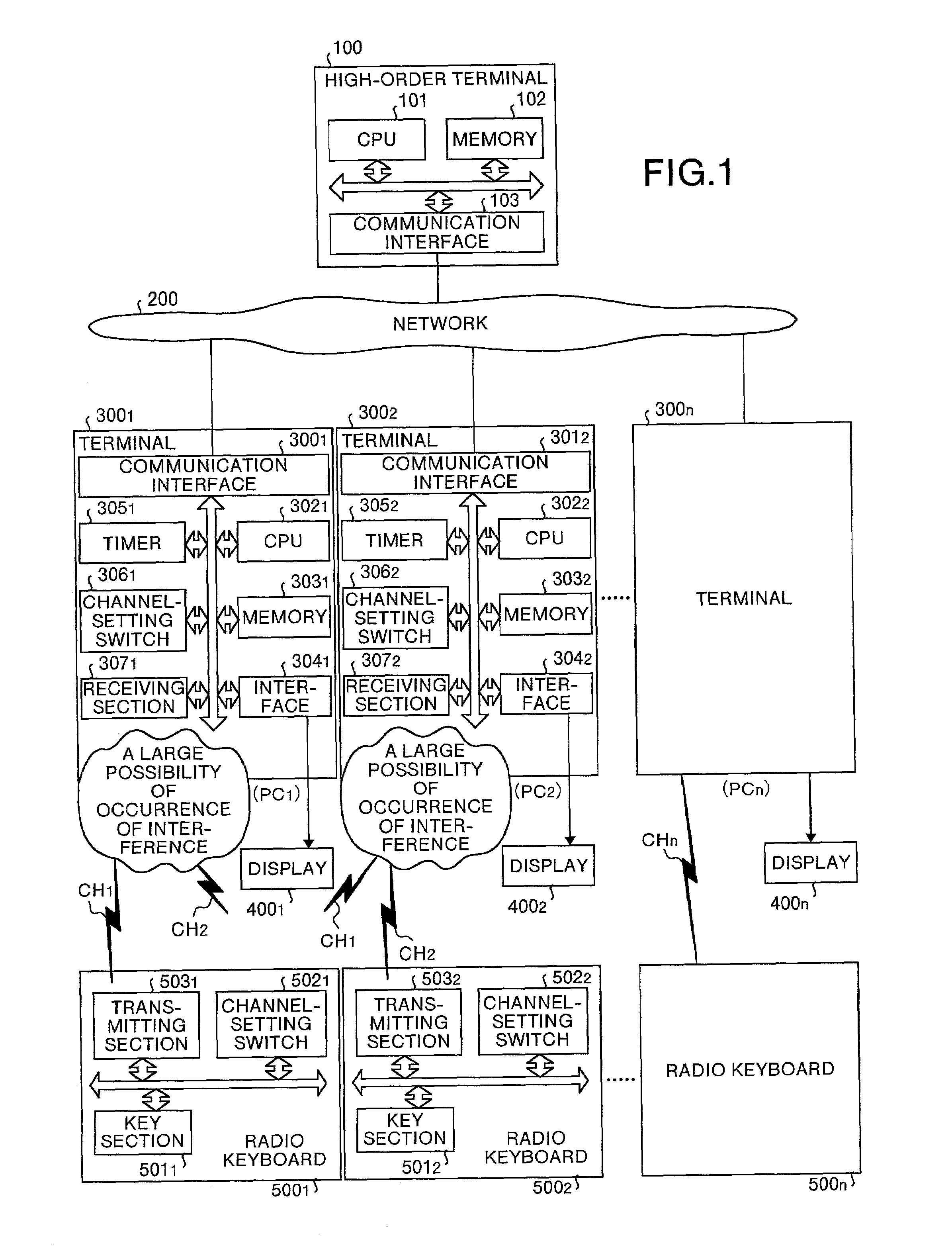
[0065]FIG. 1 is a block diagram showing a structure of the present invention. FIG. 1 shows a multi-channel input system that has a plurality of terminals connected to a plurality of radio keyboards corresponding to these terminals via radio links based on a multi-channel system, for enabling a high-order terminal to manage the setting of the plurality of channels, and catch the interference status of the channels.

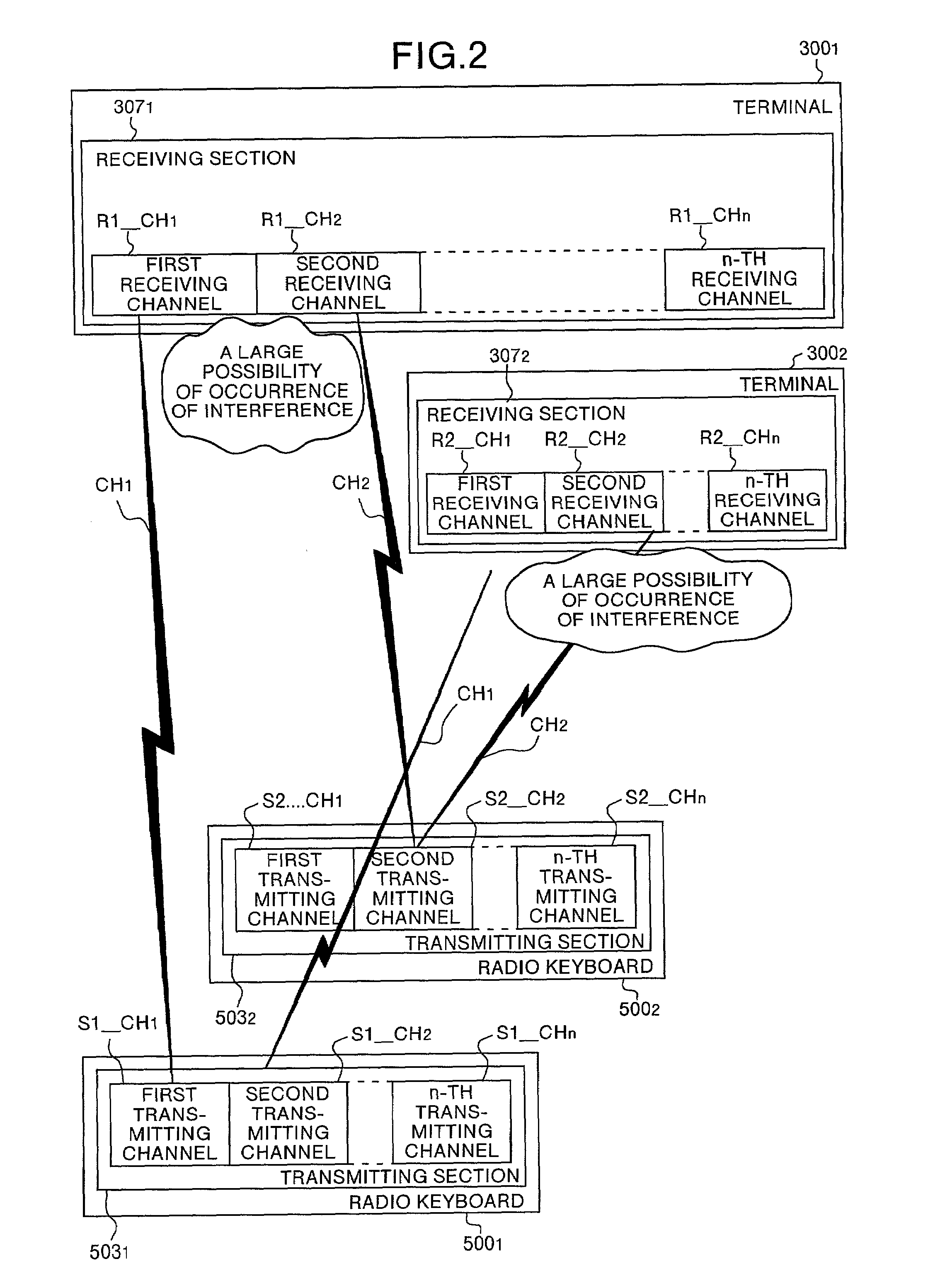
[0066]Specifically, the multi-channel input system is constructed of a high-order terminal 100 for managing the setting of channels CH1 to CHn (refer to FIG. 2) and catching a channel interference status, n terminals 3001 to 300n that are connected to the high-order terminal 100 via a network 200, displays 4001 to 400n that are connected to these terminals 3001 to 300n respectively, and n radio keyboards 5001 to 500n corresponding to the terminals 3001 to 300n respectively. In this multi-channel input system, key data are transmitted and received in the units of terminals a...

second embodiment

[0162]FIG. 13 is a block diagram showing a structure of the present invention. In this drawing, portions corresponding to those shown in FIG. 1 are attached with like reference numbers. In FIG. 13, a multi-channel input system is constructed of a high-order terminal 700 for managing the setting of channels CH1 to CHn (refer to FIG. 2) and catching a channel interference status, n terminals 8001 to 800n that are connected to the high-order terminal 700 via a network 200, displays 4001 to 400n that are connected to these terminals 8001 to 800n respectively, and n radio keyboards 9001 to 900n corresponding to the terminals 8001 to 800n respectively.

[0163]The high-order terminal 700 is a personal computer for managing the setting of the channels CH1 to CHn and catching a channel interference status. The high-order terminal 700 can communicate with the terminals 8001 to 800n via the network 200. In this high-order terminal 700, a CPU 701 executes the management of the setting of the chan...


PUM


Abstract

A multi-channel input system connects between a plurality of terminals and a plurality of radio keyboards corresponding to these terminals by radio links (channels), according to a multi-channel system. A high-order terminal has a CPU that manages a setting status of each channel in this multi-channel input system, by using a channel-setting table, and notifies the setting status to any one of the terminals a according to a request from this terminal.

Description

FIELD OF THE INVENTION[0001]The present invention relates to a technology suitable for application to a multi-channel input system for making cordless connection between a plurality of terminals and a plurality of input apparatuses corresponding to these terminals based on a multi-channel system. This invention particularly relates to a technology for preventing interference in multi-channel communications and carrying out a channel setting quickly and accurately.BACKGROUND OF THE INVENTION[0002]FIG. 22 is a block diagram showing a structure of a conventional multi-channel input system. FIG. 22 shows a structure of a conventional multi-channel input system having a plurality of terminals and a radio keyboard corresponding to each terminal. The terminal and its corresponding keyboard are connected to each other via radio links according to a multi-channel system.[0003]Specifically, the multi-channel input system is constructed of n terminals 101 to 10n, and n radio keyboards 201 to 2...

Claims


Application Information

Patent Timeline
IPC IPC(8): H04B1/18G06F3/023H04L12/28H04B7/26H04W28/04H04W48/08H04W68/00H04W72/00
CPCG06F3/023G06F3/0231H04W48/08H04W72/00H04W68/00H04W28/04
Inventor GUNJI, MASAOSAITO, KOJI
Owner FUJITSU LTD
Learn More