
Magnetic Resonance Imaging Compatible Mobile Computing Device

Active Publication Date: 2017-08-17
NEOCOIL
View PDF24 Cites 4 Cited by
  • Summary
  • Abstract
  • Description
  • Claims
  • Application Information

AI Technical Summary

Benefits of technology

The present invention is about a mobile computer that can be used in an MRI scanner without causing any harm to the patient or affecting the quality of the MRI image. The device has been tested in specific MRI environments and has been found to be safe and reliable. The mobile computer is designed to minimize interference with the MRI scanner and its components, including the display and printed circuit board, are made of non-ferrous materials. The device also includes a means for preventing interference between the MRI scanner and the user interface, such as a touchscreen.

Problems solved by technology

However, the MRI environment creates numerous challenges that make conventional electronic devices unusable in the MRI environment.
The static magnetic field generated by the MRI scanner may, at a minimum, interfere with these devices, and at worst, pull the devices into the bore of the scanner, potentially injuring the patient.
Further, non-magnetic metal components may be susceptible to electromagnetic interference once exposed to the MRI's strong dynamic magnetic fields, causing the device to malfunction or even destroying it.
The electronic device-itself could also interfere with the sensitive MRI imaging.
These long wire runs raise the potential of both radiating electromagnetic interference detectable by the MRI scanner due to signals transmitted on the wire and receiving interference from the MRI scanner which degrades the signal provided to the patient.
However, delivering audio-visual stimuli to the patient has been a challenge in the MRI environment without electronic devices.
However, the visual monitors are normally installed outside the bore and are difficult for the patient to see, providing a less than ideal solution.
Audio solutions have included the use of pneumatic headphones, which eliminate any electronic components but compromise the quality of the sound.

Method used


Image

  • Magnetic Resonance Imaging Compatible Mobile Computing Device
  • Magnetic Resonance Imaging Compatible Mobile Computing Device
  • Magnetic Resonance Imaging Compatible Mobile Computing Device

Examples


Embodiment Construction

[0028]The various features and advantageous details of the subject matter disclosed herein are explained more fully with reference to the non-limiting embodiments described in detail in the following description.

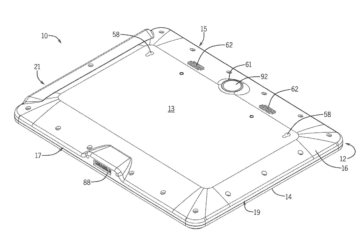
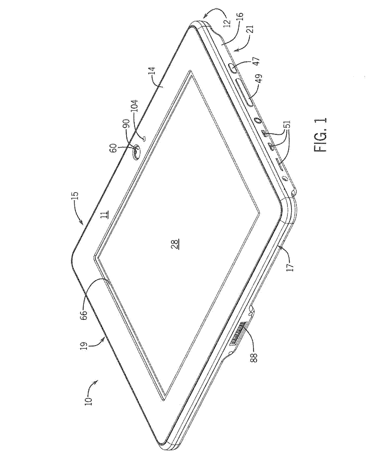
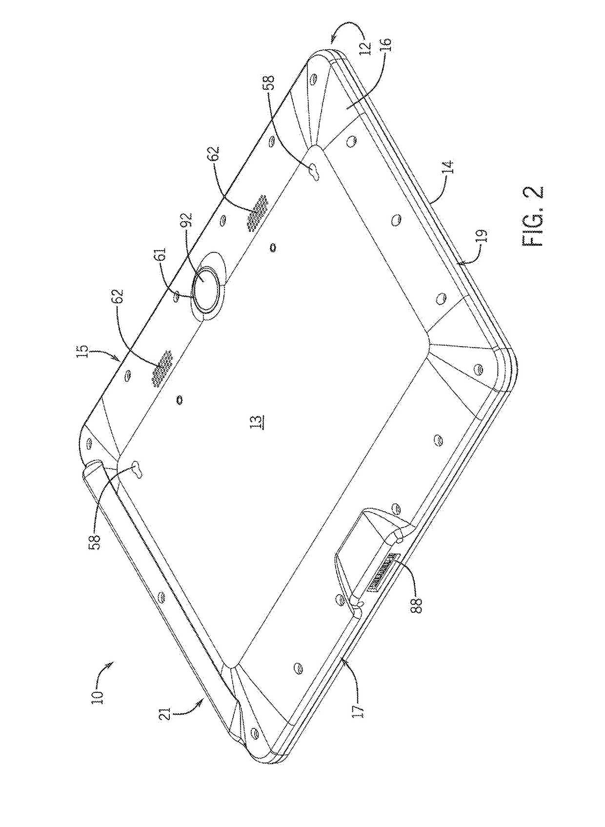
[0029]Referring to FIGS. 1 and 2, one embodiment of a mobile-computer, shown as a tablet computer 10, is illustrated. While the embodiment shown is a tablet computer 10, it is understood that the invention described herein may be applied to any wireless mobile computing device such as a laptop or mobile phone. According to the illustrated embodiment, the tablet computer 10 includes a front surface 11 and a rear surface 13 opposite the front surface 11. The tablet computer 10 further includes a top side 15 and a bottom side 17 opposite the top side 15. The tablet computer 10 also includes a left side 19 and a right side 21 opposite the left side 19. The use of the terms front, rear, top, bottom, left, or right are not intended to be limiting with respect to the location of an...


PUM


Abstract

A mobile computer suitable for use in an MRI environment is disclosed. The mobile computer includes at least one shielded cavity in which the electronics for the mobile computer are inserted. The shielded cavity inhibits undesirable emissions from the mobile computer from affecting the quality of the image obtained by the MRI scanner and inhibits electrical interference generated by the dynamic magnetic fields in the MRI scanner from affecting the performance of the mobile computer. In addition, the components used in the mobile computer are selected from non-ferrous materials and are arranged in a manner to minimize interaction between the mobile computer and the MRI scanner.

Description

CROSS-REFERENCE TO RELATED APPLICATIONS[0001]This application claims priority to U.S. Provisional. Application Ser. No. 62 / 295,374, filed Feb. 15, 2016 and titled Magnetic Resonance Imaging Compatible Mobile Computing Device, the entire contents of which is incorporated herein by reference.BACKGROUND OF THE INVENTION[0002]The subject matter disclosed herein relates to magnetic resonance imaging (MRI) “compatible” or “conditional” mobile computing devices. More specifically, tablet computers, suitable for use by a patient or technologist in a MRI environment are disclosed.[0003]As is known to those skilled in the art, an MRI system generates a strong magnetic field and detects the faint nuclear magnetic resonance (NMR) signals given off by nuclei in the presence of the magnetic field. The NMR signals are-received by antennas, also known-as coils, and transmitted to the MRI scanner for reconstruction into an MRI image. In order to provide a clear image, it is desirable to minimize ele...

Claims


Application Information

Patent Timeline
IPC IPC(8): G06F1/16G01R33/54G06F1/18
CPCG06F1/1656G01R33/546G06F1/183G06F1/1637G01R33/283G01R33/421G01R33/422G01R33/4806G06F1/1658
Inventor BROWN, BRIANHUSHEK, STEPHEN G.
Owner NEOCOIL
Learn More