Hydraulic torque wrench system

a torque wrench and hydraulic technology, applied in the field of power tools, can solve the problem that the hydraulically operated torque wrenches are not rotatably adjustabl

Inactive Publication Date: 2006-08-01
BOLTTECH MANNINGS INC
View PDF20 Cites 18 Cited by
  • Summary
  • Abstract
  • Description
  • Claims
  • Application Information

AI Technical Summary

Benefits of technology

[0026]It is an object of the invention to provide improved elements and arrangements thereof for the purposes described which is inexpensive, dependable and fully effective in accomplishing its intended purposes.

Problems solved by technology

The use of hydraulically operated torque wrenches is well known, particularly in the tightening large nuts on bolts or studs and in tight clearance installations not allowing for the travel of a long wrench handle.
Present hydraulically operated torque wrenches are not rotatably adjustable relative to the hydraulic driving cylinder, and are thus restrained from rotation by the hydraulic hoses and other appendages.

Method used


Image

  • Hydraulic torque wrench system
  • Hydraulic torque wrench system
  • Hydraulic torque wrench system

Examples


first embodiment

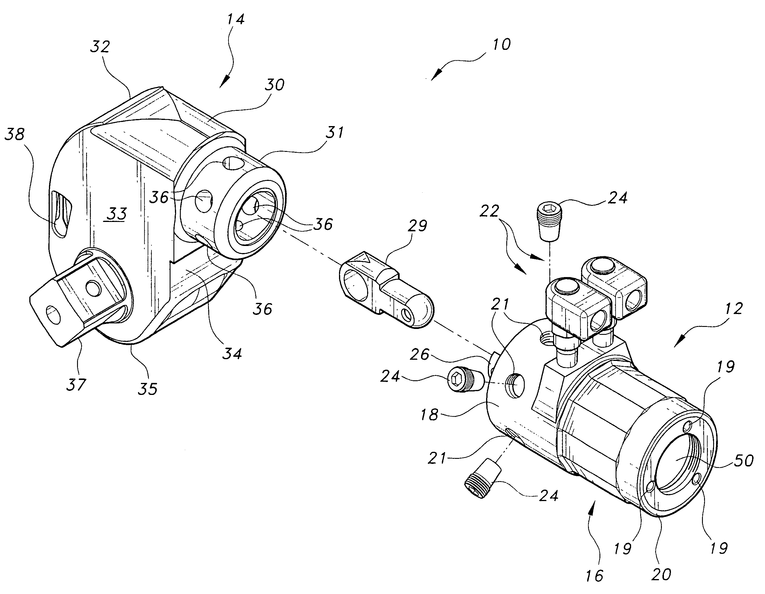
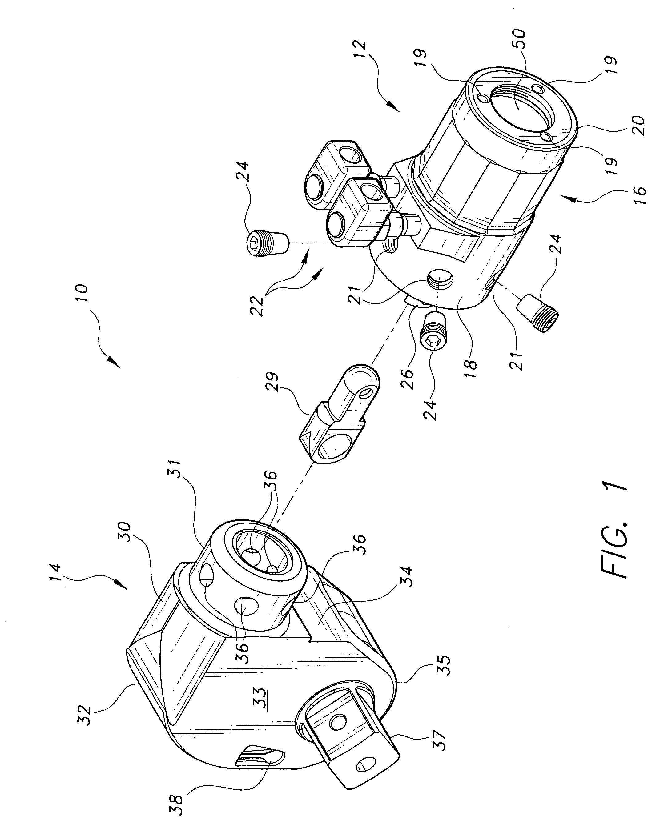
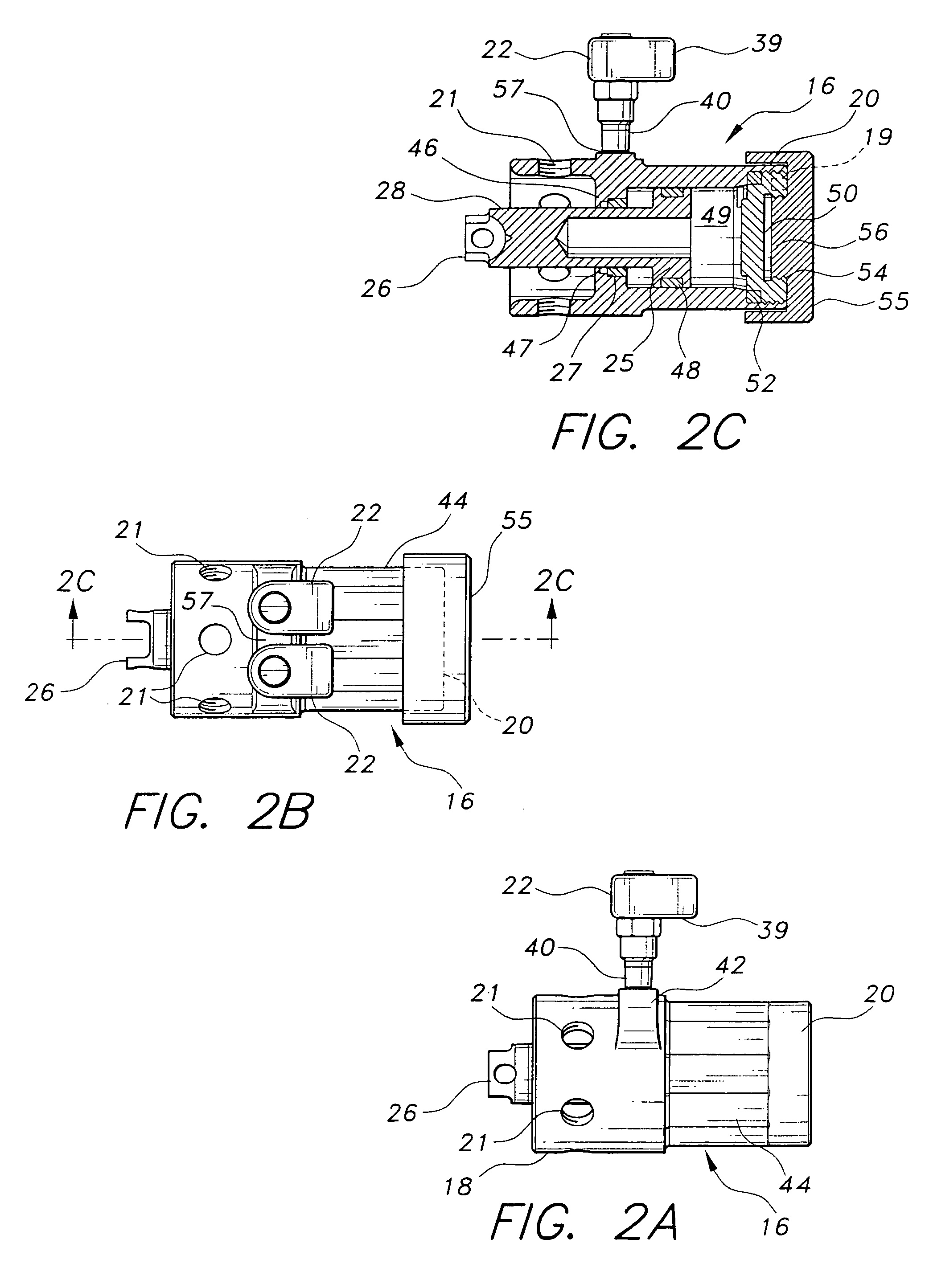
[0076]Referring more particularly to FIGS. 2A–2D, there are shown side elevation, plan, sectional, and perspective views, respectively of the hydraulic drive piston unit 12. Hydraulic cylinder unit 12 has a generally cylindrical housing 16 having a polygonal outer wall 44 and defining a coaxial hydraulic cylinder within. Cylindrical housing 16 has a hydraulic fitting boss 42 extending from the upper portion above end wall 46 and accepts hydraulic swivel fittings 40 forming the lower portion of hydraulic fittings 22, hydraulic connectors 39 providing for connection with respective hydraulic pressure hoses (not shown).

[0077]Cylinder end wall 46 and threaded end cap 50 define the front and rear ends, respectively, of the hydraulic cylinder, and piston 25 drives the connected piston rod 28 forward through the centrally mounted bushing 47 of end wall 46 when hydraulic fluid is injected into hydraulic pressure chamber 49. Piston rod seal 27 is located to the rear of adjacent bushing 47 to...

second embodiment

[0080]Referring more particularly to FIGS. 2E–2G, there is shown a perspective, and two sectional views offset from the vertical lengthwise center of the hydraulic piston drive unit 12. In this embodiment, cylinder unit body 16 has a three-way pivot hydraulic fitting 60 having opposed hydraulic connectors 62 for connection with conventional hydraulic fluid supply hoses (not shown) and having a single upright connector 61 connected with a hydraulic collar 64 encircling body 16 at cylinder end wall 46. Three axially spaced O-ring grooves 65 are machined within the outer surface of body 16 and contain O-rings 66 separating the hydraulic cylinder unit body 16 and hydraulic collar 64 into a first and a second circumferential annular hydraulic fluid passage. The single upright connector 61 is fixedly mounted on hydraulic collar 64 and has an upper concentric swivel portion 63 connected so as to swivel in either direction coaxially with the fixed portion of upright connector 61. Hydraulic ...


PUM


Abstract

A hydraulic torque wrench having a separate ratchet unit and hydraulic cylinder drive unit connectable by an overlapping cylindrical connection at selected angles of rotation providing clearance in use. The hydraulic cylinder actuates the ratchet mechanism by a connecting rod traveling through the overlapping cylindrical connection and engaging a pivotable drive plate. The ratchet may have a male drive shaft for driving a socket, or a female driver such a hex or spline wrench. The ratchet unit case may be integral, or split for removable accesses to the ratchet mechanisms. The cylinder unit hydraulic connections may be separate rotatable connections or a single connection and collar, allowing three-way rotation. Attachments for the hydraulic unit include a pipe flange spreader, a nut splitter, scissor action shears, and a lift / spreader for lifting an object from a flat surface or spreading surfaces apart. A reaction bar affixes to the drive unit body.

Description

CROSS-REFERENCE TO RELATED APPLICATION[0001]This application is a division of application Ser. No. 10 / 411,695 filed Apr. 11, 2003, now U.S. Pat. No. 6,912,933.BACKGROUND OF THE INVENTION[0002]1. Field of the Invention[0003]The present invention relates to power tools. More particularly, the present invention relates to a hydraulic cylinder actuated tool system having a single hydraulic cylinder actuator and replaceable tools including torque wrenches, shears, nut breakers, and flange spreaders.[0004]2. Description of the Related Art[0005]The use of hydraulically operated torque wrenches is well known, particularly in the tightening large nuts on bolts or studs and in tight clearance installations not allowing for the travel of a long wrench handle. Present hydraulically operated torque wrenches are not rotatably adjustable relative to the hydraulic driving cylinder, and are thus restrained from rotation by the hydraulic hoses and other appendages. It would be desirable to provide a ...

Claims


Application Information

Patent Timeline
Patent Type & Authority Patents(United States)
IPC IPC(8): B25B13/46B25B17/00B23D29/00B25B21/00B25B27/16
CPCB23D29/005B23D29/007B25B27/16B25B23/0078B25B21/005
Inventor KNOPP, BRIANKNOPP, SR., HARRY J.
Owner BOLTTECH MANNINGS INC
Why Eureka
Try Eureka