Method for detecting earth formation fractures by seismic imaging of diffractors

a technology of diffractors and seismic imaging, which is applied in the field of seismic exploration of the earths subsurface, can solve the problems of not being able to accurately detect the fractured formations of the earth formation, not being able to provide azimuthal avo data for all areas, and not being able to fit the foregoing assumptions of lateral continuity

Active Publication Date: 2006-08-01
PGS GEOPHYSICAL AS
View PDF5 Cites 33 Cited by
  • Summary
  • Abstract
  • Description
  • Claims
  • Application Information

AI Technical Summary

Problems solved by technology

It is known in the art that some types of subsurface Earth structures do not fit the foregoing assumptions of lateral continuity and horizontal layering.
In particular, so-called “fractured” formations typically are not well represented by a model based on laterally continuous, horizontally layered media.
However, azimuthal AVO data are not available for all areas.
Furthermore, azimuthal AVO has not proven to be particularly effective in marine seismic data recording and analysis, unless some specially designed recording methods and systems are used, for example, four component (4C) ocean bottom cables (OBCs).
However, OBC data are not available in all areas, and acquisition and processing of OBC data continues to be relatively difficult and expensive.

Method used


Image

  • Method for detecting earth formation fractures by seismic imaging of diffractors
  • Method for detecting earth formation fractures by seismic imaging of diffractors
  • Method for detecting earth formation fractures by seismic imaging of diffractors

Examples


Embodiment Construction

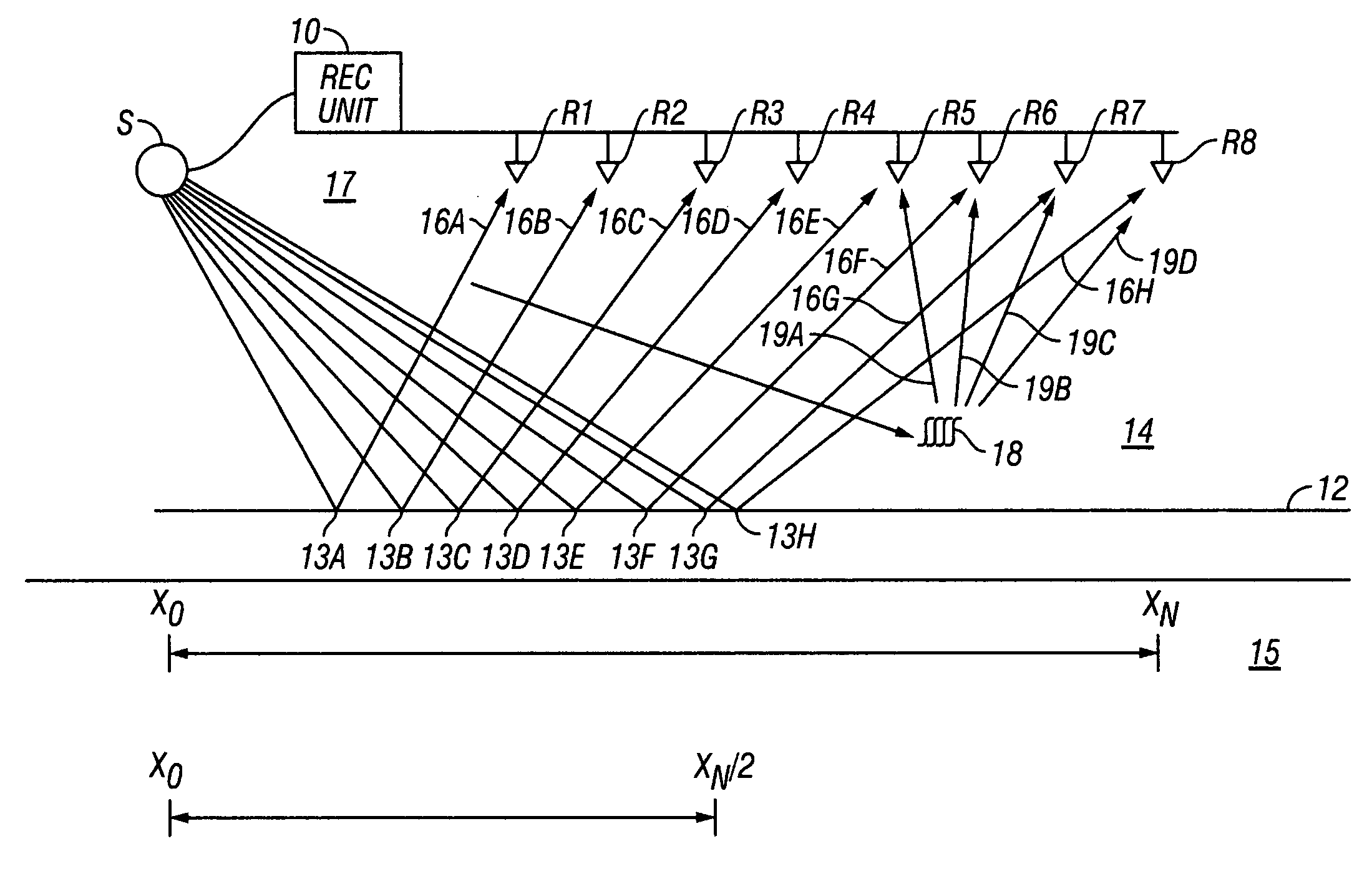
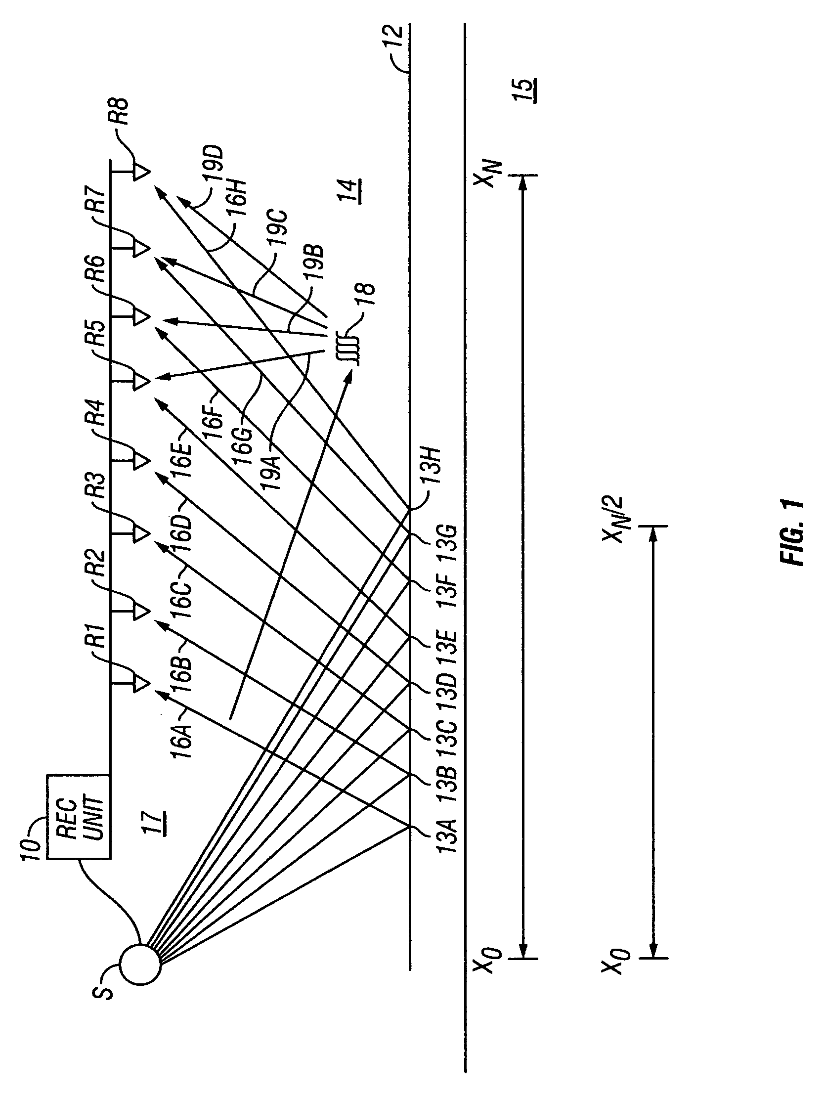
[0024]An example of seismic data acquisition is shown schematically in FIG. 1. A seismic recording unit 10 is placed at a selected position on the Earth's surface. The recording unit 10 includes various control and recording devices (not shown separately) of types well known in the art including a source controller, acquisition controller and multi-channel data recorder. The source controller (not shown separately) is coupled operatively, either by cable as shown in FIG. 1 or by radio telemetry (not shown in FIG. 1), to one or more seismic energy sources, shown generally at S. The source S may be a vibrator, explosive, air gun, water gun or and array of such guns depending on the particular data acquisition arrangement used and whether the acquisition is being performed on land or in a body of water. Any type of seismic energy source known in the art may be used with the invention, and accordingly, the type of source S is not a limitation on the scope of the invention.

[0025]A plural...


PUM


Abstract

A method is disclosed for seismic imaging of subsurface diffractors. The method includes performing migration velocity analysis on a seismic time record section and depth migrating the time section for offsets exceeding one-half a distance between a seismic energy source and a seismic receiver most distant from the source during acquisition of seismic data used to generate the time record section.

Description

CROSS-REFERENCE TO RELATED APPLICATIONS[0001]Not applicable.STATEMENT REGARDING FEDERALLY SPONSORED RESEARCH OR DEVELOPMENT[0002]Not applicable.BACKGROUND OF THE INVENTION[0003]1. Field of the Invention[0004]The invention relates generally to the field of seismic exploration of the Earth's subsurface. More particularly, the invention relates to methods for processing seismic signals for the purpose of identifying and / or locating fractures in the Earth's subsurface.[0005]2. Background Art[0006]Seismic exploration of the Earth's subsurface is used for, among other purposes, determining the structure, mineral composition and / or fluid content of subsurface formations. Generally, seismic exploration methods known in the art include deploying one or more seismic energy sources at selected positions on or near the Earth's surface, and deploying an array of seismic sensors on or near the Earth's surface at known positions proximate to the seismic energy source(s). When seismic exploration i...

Claims


Application Information

Patent Timeline
Patent Type & Authority Patents(United States)
IPC IPC(8): G01V1/28G01V1/00G01V1/30
CPCG01V1/28G01V1/303G01V2210/51
Inventor TANER, M. TURHANLANDA, EVGENY
Owner PGS GEOPHYSICAL AS
Why Eureka
Try Eureka