Method for determining wellbore position using seismic sources and seismic receivers

a technology of seismic receiver and wellbore, which is applied in the direction of instruments, borehole/well accessories, surveys, etc., can solve the problems of increasing the risk of collision between a wellbore and an adjacent wellbore, requiring expensive and time-consuming replacement of the wellbore, and less accurate wellbore position determination

Active Publication Date: 2011-05-05
SCHLUMBERGER TECH CORP
View PDF18 Cites 36 Cited by
  • Summary
  • Abstract
  • Description
  • Claims
  • Application Information

AI Technical Summary

Problems solved by technology

Using the foregoing surveying techniques, however, can result in wellbore position determination that becomes less accurate with increasing lateral distance from the surface position of the wellbore.
Less certainty in positioning the wellbore can result, for example, in increased risk of collision of a wellbore with an adjacent wellbore in cases where a plurality of wellbores are drilled from a single surface location or similar cases where wellbores are proximate each other.
Loss of positional accuracy may result in one or more target reservoirs not being penetrated by the wellbore, which may require expensive and time consuming replacement of the wellbore to penetrate such targets.

Method used


Image

  • Method for determining wellbore position using seismic sources and seismic receivers
  • Method for determining wellbore position using seismic sources and seismic receivers
  • Method for determining wellbore position using seismic sources and seismic receivers

Examples


Embodiment Construction

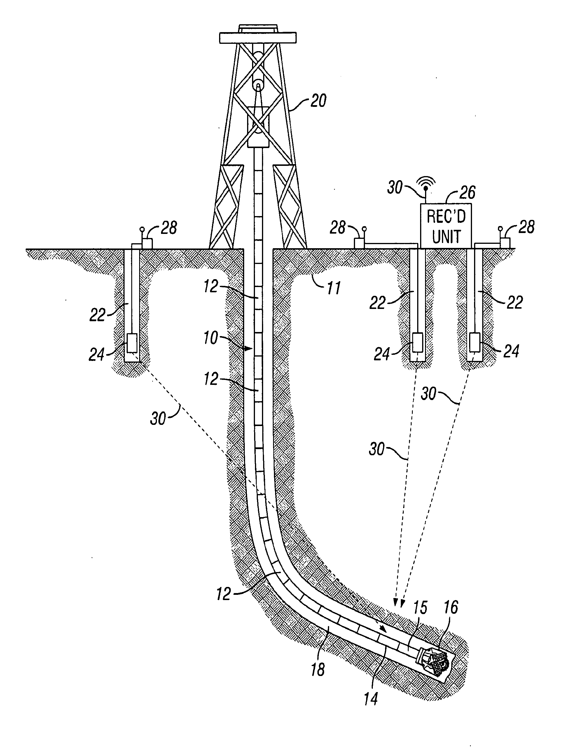
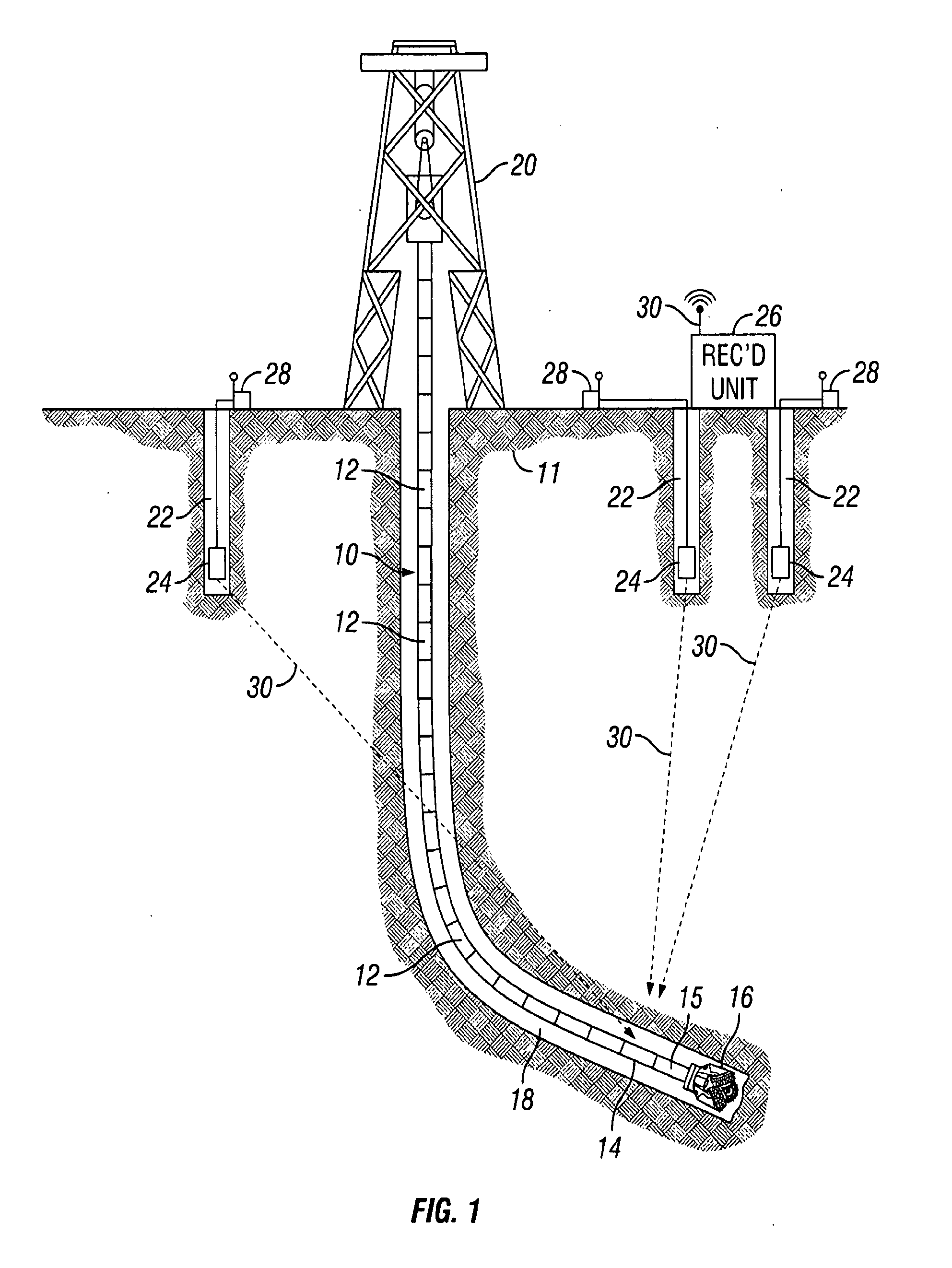
[0018]FIG. 1 shows a simplified schematic diagram of a wellbore 18 being drilled through subsurface rock formations 11. Drilling can be performed using a drill string 10 assembled from threadedly coupled sections or “joints”12 of pipe suspended in the wellbore 18 by a hoisting unit called a drilling rig 20. A drill bit 16 is disposed at the lower end of the drill string 10 to drill through the rock formations 11, thereby extending or deepening the wellbore 18. The drill string 10 may include proximate its lower end a logging while drilling (“LWD”) instrumentation package 14 of types well known in the art. Such LWD instrumentation package 14 may include a seismic sensor 15 therein. One example of a seismic sensor included in a LWD instrumentation package is used to provide services under the trademark SEISMIC VISION, which is a trademark of the assignee of the present invention. Alternatively, a seismic sensor (not shown) may be removably inserted into the drill string 10 to about th...


PUM


Abstract

A method for determining position of a wellbore in the Earth's subsurface includes actuating a plurality of seismic energy sources each disposed at a known geodetic position. Seismic energy from the sources is detected at a selected location along the wellbore. The geodetic position at the selected location is determined from the detected seismic energy. A corresponding method includes actuating a seismic energy source at a selected position within the wellbore. The seismic energy is detected at a plurality of known geodetic positions. The geodetic position of the source is determined from the detected seismic energy.

Description

CROSS-REFERENCE TO RELATED APPLICATIONS[0001]Priority is claimed from U.S. Provisional Application No. 61 / 042,966 filed on Apr. 7, 2008.STATEMENT REGARDING FEDERALLY SPONSORED RESEARCH OR DEVELOPMENT[0002]Not applicable.BACKGROUND OF THE INVENTION[0003]1. Field of the Invention[0004]The invention relates generally to the field of directional drilling of wellbores through subsurface rock formations. More particularly, the invention relates to techniques for determining the geodetic trajectory and position of a directionally drilled wellbore using seismic techniques.[0005]2. Background Art[0006]Wellbores drilled through subsurface rock formations are used for, among other purposes, extracting oil and gas from subsurface reservoirs. Many wellbores are drilled to have a selected trajectory, that is to say, along a selected geodetic path through the subsurface other than substantially vertical, using various techniques known collectively as “directional drilling.” Directional drilling en...

Claims


Application Information

Patent Timeline
Patent Type & Authority Applications(United States)
IPC IPC(8): E21B47/022G01V1/50
CPCG01V1/42E21B47/02208E21B47/0224
Inventor POEDJONO, BENNY
Owner SCHLUMBERGER TECH CORP
Why Eureka
Try Eureka