

Multiple attenuation method
a multi-attenuation and multi-frequency technology, applied in seismology, seismology, instruments, etc., can solve the problem of multiples themselves generating ghost events
- Summary
- Abstract
- Description
- Claims
- Application Information
AI Technical Summary
Benefits of technology
Problems solved by technology
Method used
Image

Examples
Embodiment Construction
[0029]In a first step in accordance with the present invention, a marine seimic survey is performed that includes the step of essentially repeating the survey, and hence, the source and receiver positions with different traveltimes for signal between the sea surface and the receiver positions.
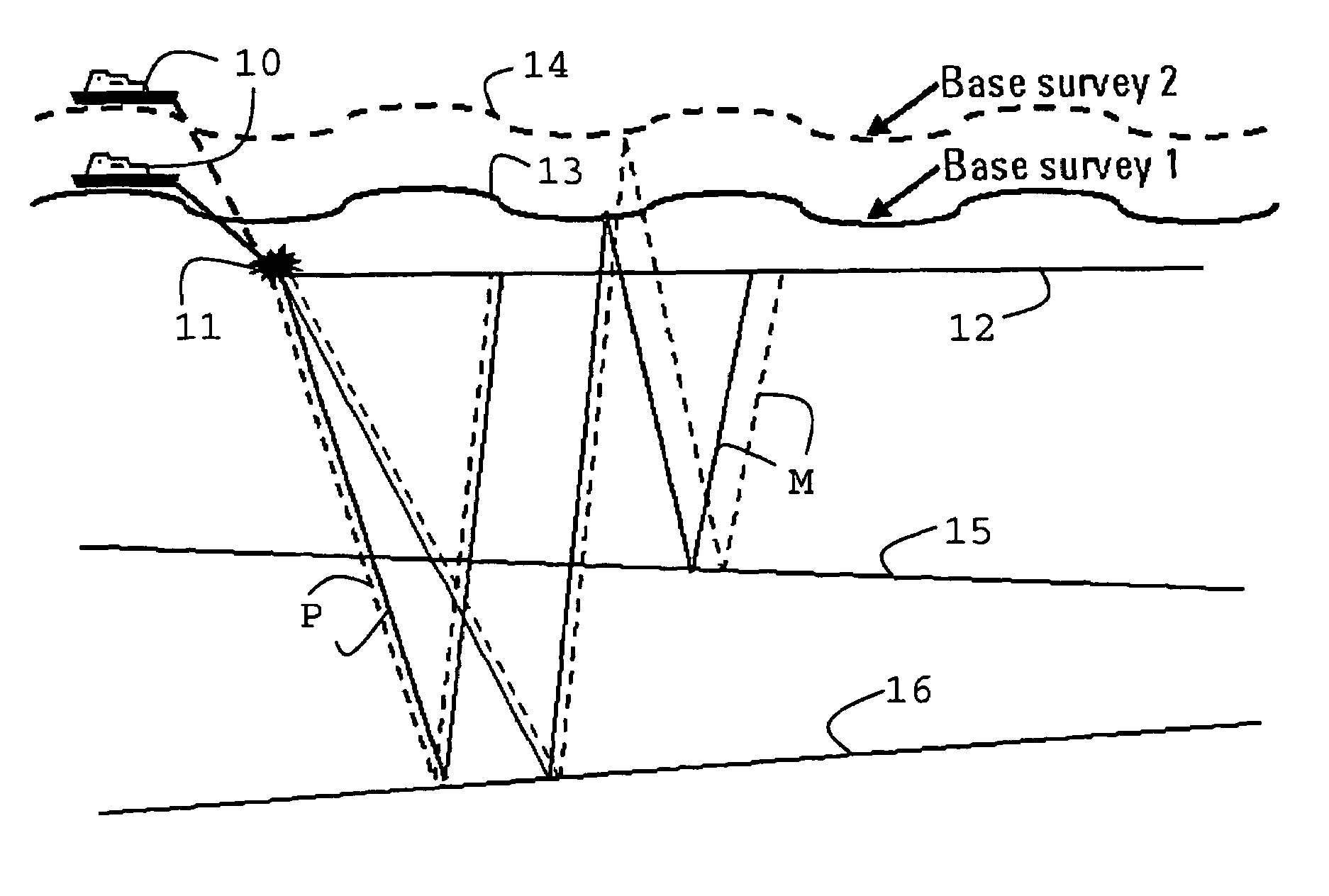
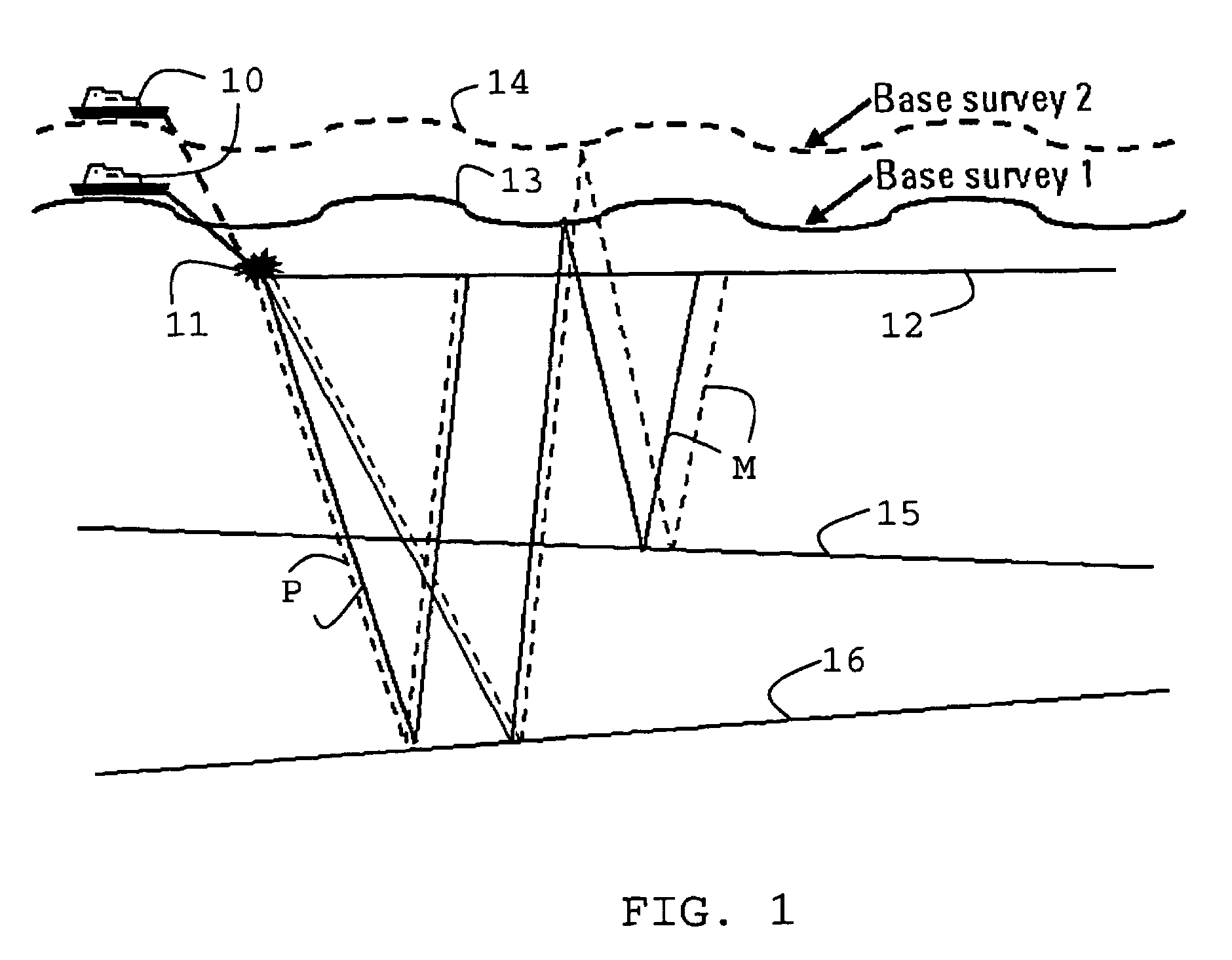
[0030]For a conventional survey using a towed streamer configuration, a possible survey is illustrated in FIG. 1A.
[0031]In FIG. 1A, an exploration vessel 10 towing seismic sources 11 and receiver arrays (streamers) 12 is showing performing an otherwise essentially identical survey at two different tidal conditions. During the first survey the sea surface is shown as solid line 13. During the second survey the sea surface is shown as dashed line 14. The two surveys are performed over the same section of seabed 15 and both, source 11 and streamer 12 are shown at identical positions during both surveys with vessel 10 at two different heights relative to seafloor 15. The configuration shown can be ...
PUM
 Abstract
Description
Claims
Application Information