Method for continuous sensor self-test

a sensor and self-testing technology, applied in the direction of instruments, liquid/fluent solid measurement, using mechanical means, etc., can solve the problem of identifying the malfunction of the sensor

Active Publication Date: 2006-08-08
ANALOG DEVICES INC
View PDF7 Cites 31 Cited by
  • Summary
  • Abstract
  • Description
  • Claims
  • Application Information

AI Technical Summary

Problems solved by technology

If an unexpected response is detected from the sensor, a malfunction of the sensor may be identified.

Method used


Image

  • Method for continuous sensor self-test
  • Method for continuous sensor self-test
  • Method for continuous sensor self-test

Examples


Embodiment Construction

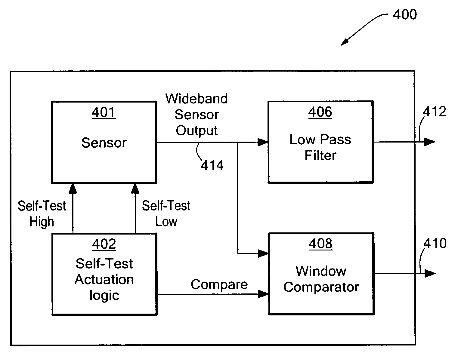
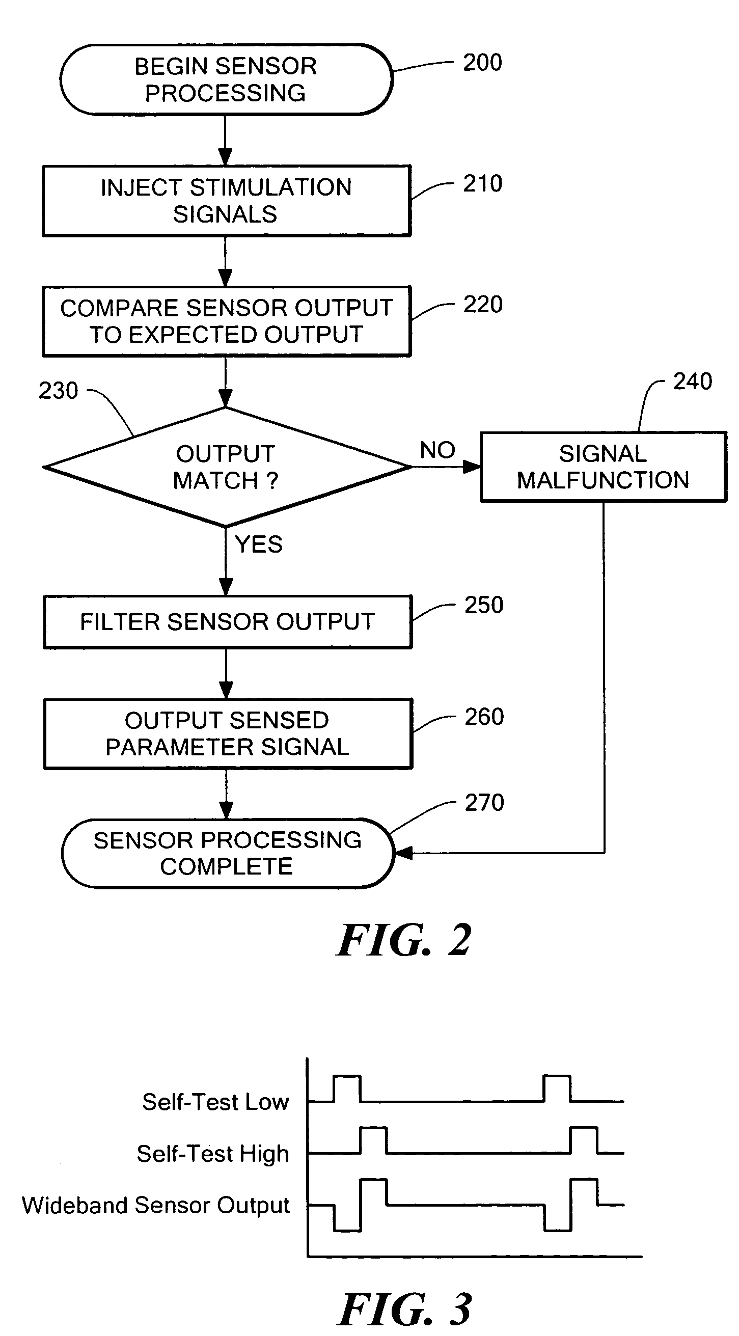
[0015]In various embodiments of the present invention, a method of continuously testing sensors is provided. The method includes stimulating a sensor at high frequency and looking for appropriate sensor output response. A subsequent low pass filter can remove the response to the high-frequency self-test signal from the sensor output and allow a sensed parameter to be determined.

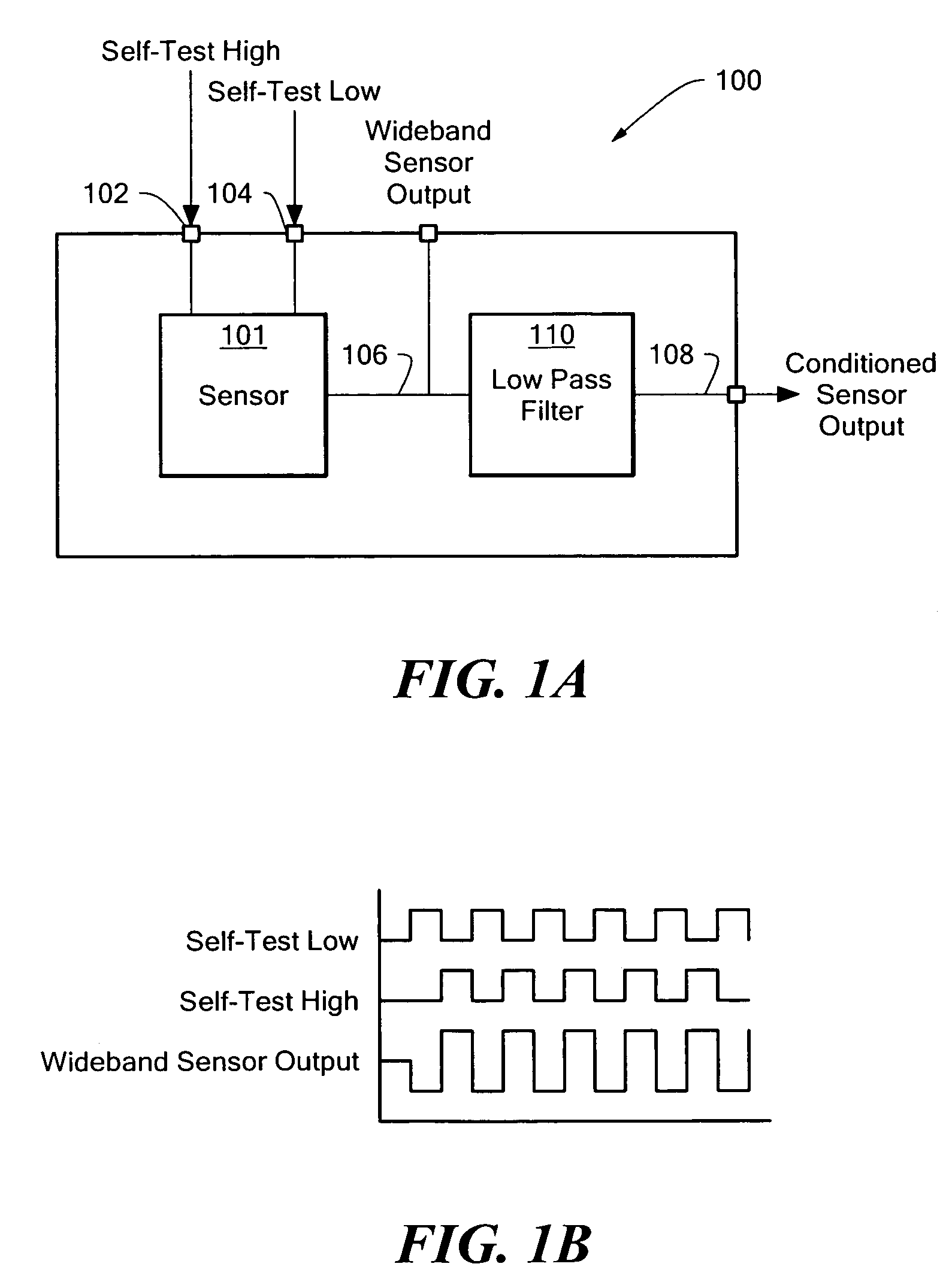
[0016]FIG. 1A shows an exemplary sensor system 100 according to an embodiment of the invention. A sensor 101, for example, an accelerometer or a gyroscopic sensor, is provided that includes complementary self-test inputs. As used in this specification and in any appended claims, “complementary self-test inputs” will mean inputs where a self-test stimulus input 102 causes an increase in sensor output while another self-test stimulus 104 causes a decrease in output. These complementary self-test stimuli may be toggled at high speeds, using for example, square waves inputs to the sensor that are 180 degrees out ...


PUM


Abstract

A method and device for self-test of a sensor. The method includes stimulating the sensor with signals that generate sensor outputs at a frequency that differs from the frequency of expected sensed parameter signals. The sensor output is filtered to remove the effects of the stimulation inputs, generating a sensed parameter signal. The unfiltered sensor output is compared to the expected output of the sensor with the stimulus input. A malfunctioning sensor may be detected by the comparison and appropriate action may then be taken.

Description

TECHNICAL FIELD[0001]The present invention relates to methods of self-test for sensors and, particularly, for micromachined capacitive sensors.BACKGROUND[0002]Micromachined accelerometers can be used to sense acceleration for a variety of applications, including sensing the acceleration that occurs as a result of an automobile accident in order to trigger an air bag, or sensing the acceleration resulting from an earthquake in order to automatically shut off a gas line to prevent fires.[0003]In one type of micromachined device, a polysilicon mass is suspended over a substrate by supporting tethers. The mass, which is essentially parallel to the substrate, has a beam elongated along an axis, and a number of fingers that extend away from the beam in a direction perpendicular to the axis of the beam. The beam and fingers are movable laterally relative to the substrate along the axis. Each of these movable fingers is positioned between two polysilicon fingers that are in the plane of the...

Claims


Application Information

Patent Timeline
Patent Type & Authority Patents(United States)
IPC IPC(8): G01P9/04G01D3/08G01D18/00G01D21/00
CPCG01D3/08G01D21/00G01D18/002
Inventor WEINBERG, HARVEYGEEN, JOHN A.
Owner ANALOG DEVICES INC
Why Eureka
Try Eureka