
Test apparatus for a waveguide sensing level in a container

a technology of waveguide sensing and test apparatus, which is applied in the direction of machines/engines, using reradiation, instruments, etc., can solve the problems of fluid loss from the container, operator's inability to tell the difference, and unchanging transmitters

Active Publication Date: 2006-08-08
ROSEMOUNT INC
View PDF13 Cites 37 Cited by
  • Summary
  • Abstract
  • Description
  • Claims
  • Application Information

AI Technical Summary

Benefits of technology

Enables operators to reliably determine if an unchanging transmitter output is due to a malfunction or an actual unchanging level, preventing fluid loss or overfilling by providing a clear diagnostic indication, thus ensuring accurate level monitoring.

Problems solved by technology

An operator may not be able to tell the difference between an unchanging transmitter output that accurately indicates an unchanging fluid level and an unchanging transmitter output that is stuck at a fixed output value because the waveguide or level transmitter is malfunctioning.
A localized build-up of contamination on the waveguide, for example, can cause such a malfunction.
If a level output is stuck, then fluid can be lost from the container, or the container can be overfilled, without any warning to the operator.

Method used


Image

  • Test apparatus for a waveguide sensing level in a container
  • Test apparatus for a waveguide sensing level in a container
  • Test apparatus for a waveguide sensing level in a container

Examples


first embodiment

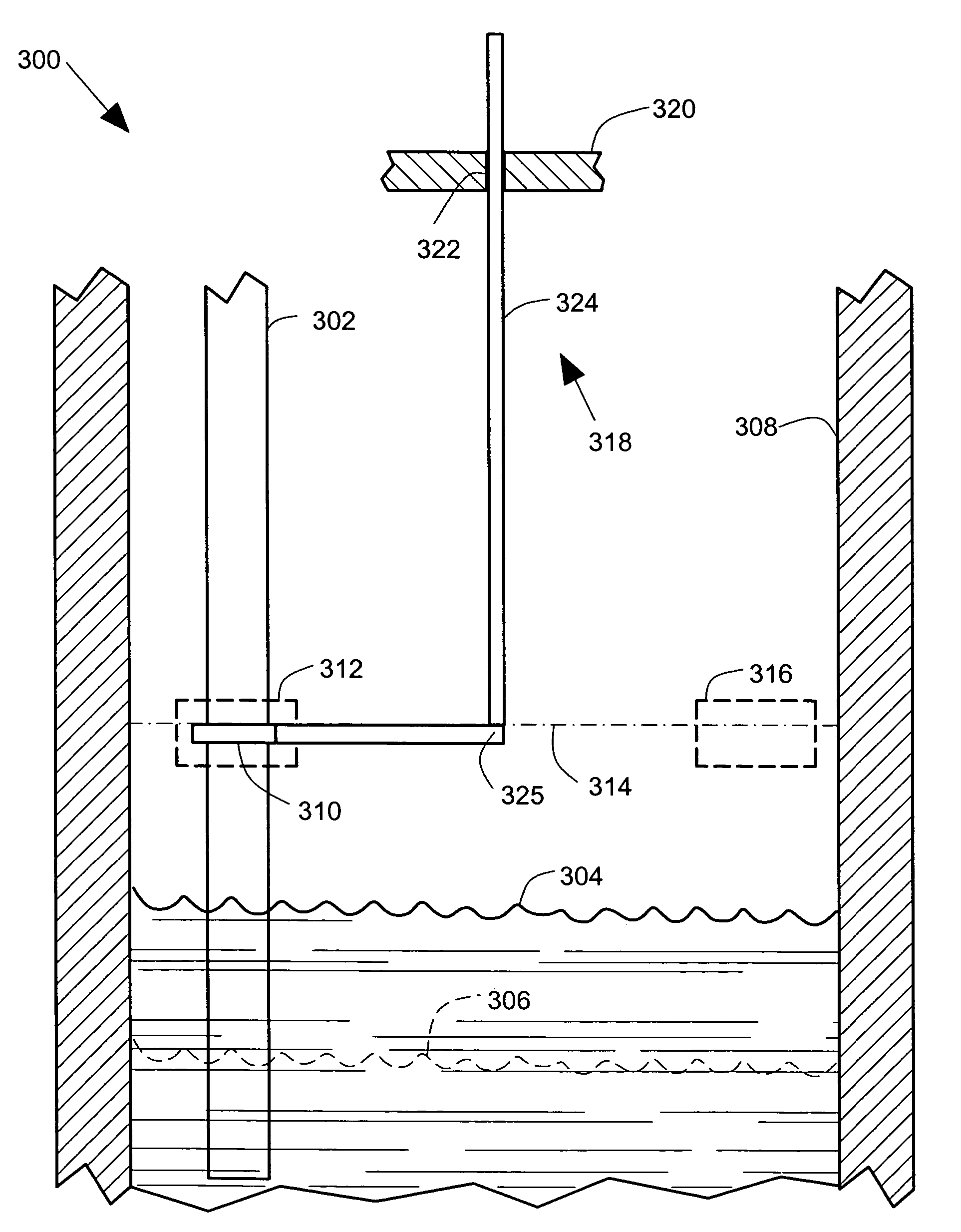
[0024]FIG. 3 illustrates a block diagram of a test apparatus 300 for testing a waveguide 302 that senses variable levels such as levels 304, 306 in a container 308. The test apparatus 300 comprises a bridge 310 that has a test position 312 in which the bridge 310 is close to the waveguide 302 and bridges the waveguide 302 to simulate a simulated level 314. The simulated level 314 is preferably higher than the highest of the sensed levels 304, 306. The bridge 310 also has a storage position 316 that is remote from the waveguide 302 in which the bridge 310 does not bridge the waveguide 302. The waveguide 302 preferably comprises a pair of generally parallel conductors. The bridge 310 preferably comprises a bar that bridges the parallel conductors in the test position 312.

[0025]The term “bridge” as used in the application means providing an electromagnetic discontinuity at a simulated level along the waveguide that reflects a simulated level signal back along the waveguide to a transmi...

second embodiment

[0030]FIG. 4 pictorially illustrates an illustrative test apparatus 400 for testing a waveguide 402 that senses variable levels such as level 404 in a container. A level transmitter 440 includes a transmitter electronics housing 442 and a transmitter mounting flange 444. The waveguide 402 passes through the transmitter mounting flange 444 and connects to the level transmitter 440.

[0031]A container 446 includes a container flange 448 that includes a flange opening 450 that provides access inside the container 446 for installing the waveguide 402 and the test apparatus 400. The transmitter mounting flange 444 is bolted to the container flange 448 by bolts 452. The transmitter mounting flange 444 also includes a round through hole 454 that is off center, but is aligned with the flange opening 450.

[0032]The test apparatus 400 comprises a bridge 410 that is shown in a test position 412 in which the bridge 410 is close to the waveguide 402 and bridges the waveguide 402 to simulate a simul...


PUM


Abstract

A test apparatus for a waveguide that senses levels in a container. The test apparatus includes a bridge with a test position where the bridge bridges the waveguide to simulate a simulated level. The bridge also has a storage position. The test apparatus also has an actuator coupled to the bridge that moves the bridge between the test and storage positions.

Description

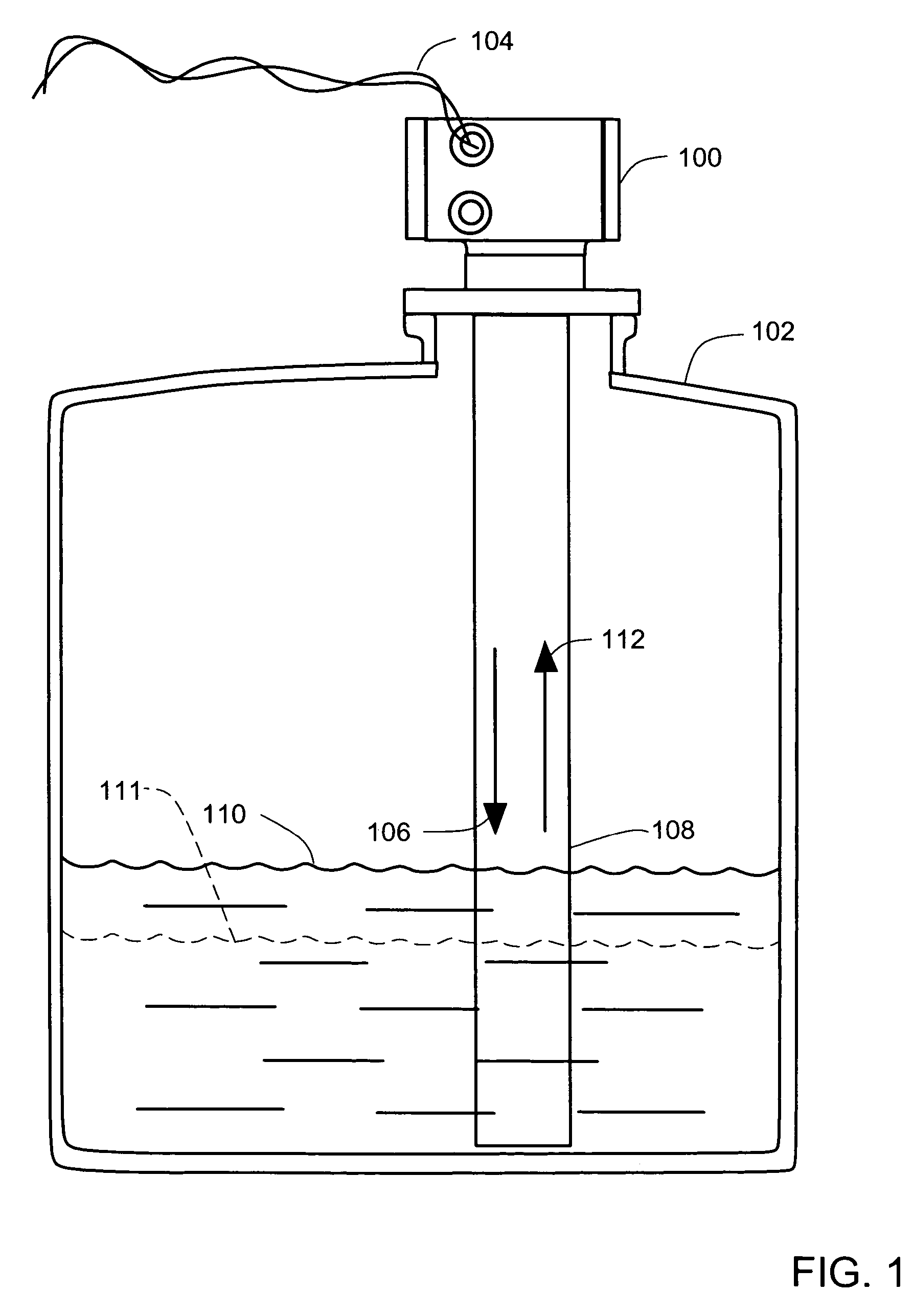
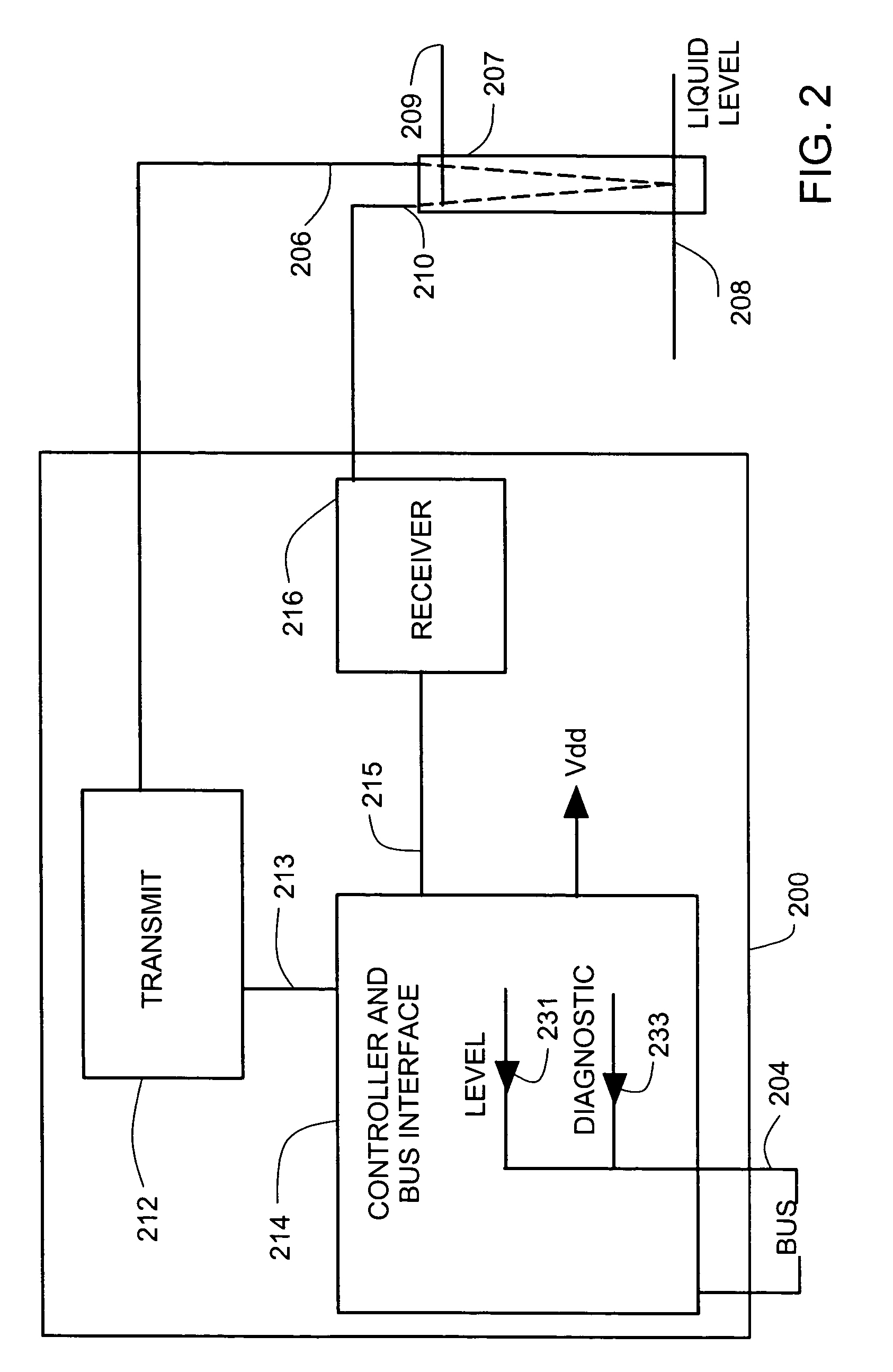
BACKGROUND OF THE INVENTION[0001]Level transmitters that transmit and receive reflected electromagnetic pulses along a waveguide in a container are known. These level transmitters provide one or more local or remote outputs that indicate a fluid level in the container.[0002]The fluid level in a storage container, and also the transmitter outputs can remain unchanged for long periods of time. An operator may not be able to tell the difference between an unchanging transmitter output that accurately indicates an unchanging fluid level and an unchanging transmitter output that is stuck at a fixed output value because the waveguide or level transmitter is malfunctioning. A localized build-up of contamination on the waveguide, for example, can cause such a malfunction. If a level output is stuck, then fluid can be lost from the container, or the container can be overfilled, without any warning to the operator.[0003]A method and an apparatus are needed to enable an operator to reliably as...

Claims


Application Information

Patent Timeline
Patent Type & Authority Patents(United States)
IPC IPC(8): G01F23/284G01F25/00
CPCG01F25/0061G01F23/284G01F25/20
Inventor SMITH, LEE MICHAEL
Owner ROSEMOUNT INC
Learn More