Clamp circuit for clamping a digital video signal

a technology of digital video signal and clamping circuit, which is applied in the field of clamping circuit, can solve the problems of difficult matching of pedestal level, image disturbance, and inability to guarantee that the video signal is securely suppressed at or below a reference level

Inactive Publication Date: 2006-08-22
RENESAS ELECTRONICS CORP
View PDF11 Cites 10 Cited by
  • Summary
  • Abstract
  • Description
  • Claims
  • Application Information

AI Technical Summary

Problems solved by technology

Therefore, even if the video signal is clamped, there is no guarantee that the video signal is securely suppressed at or below a reference level necessary for the digital signal processing.
In other words, by merely clamping the video signal, it is difficult to match the pedestal level.
When the pedestal level varies, combing or flicker occurs and the image is disturbed.
The image with the combing or flicker occurring therein not only is hard to see, but also exerts a bad influence on eyes.
When the error range of the pedestal level is made small in the conventional art, however, the pedestal level frequently varies.
This results in a problem that occurrence of the combing or flicker cannot be completely prevented.
When the number of times of pedestal level quantization in a field is small, or when the number of bits in quantization is small, the computation error becomes large and the pedestal level frequently varies.
This results in a problem that the number of times of sampling must be increased and the number of bits in quantization must be increased.
This results in a problem that the circuit scale becomes large.

Method used


Image

  • Clamp circuit for clamping a digital video signal
  • Clamp circuit for clamping a digital video signal
  • Clamp circuit for clamping a digital video signal

Examples


Embodiment Construction

[0015]Exemplary embodiments of a clamp circuit according to the present invention are explained in detail below with reference to the accompanying drawings.

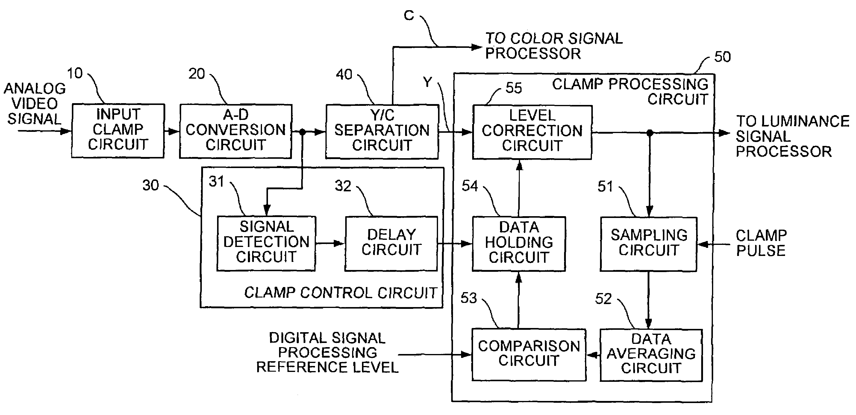
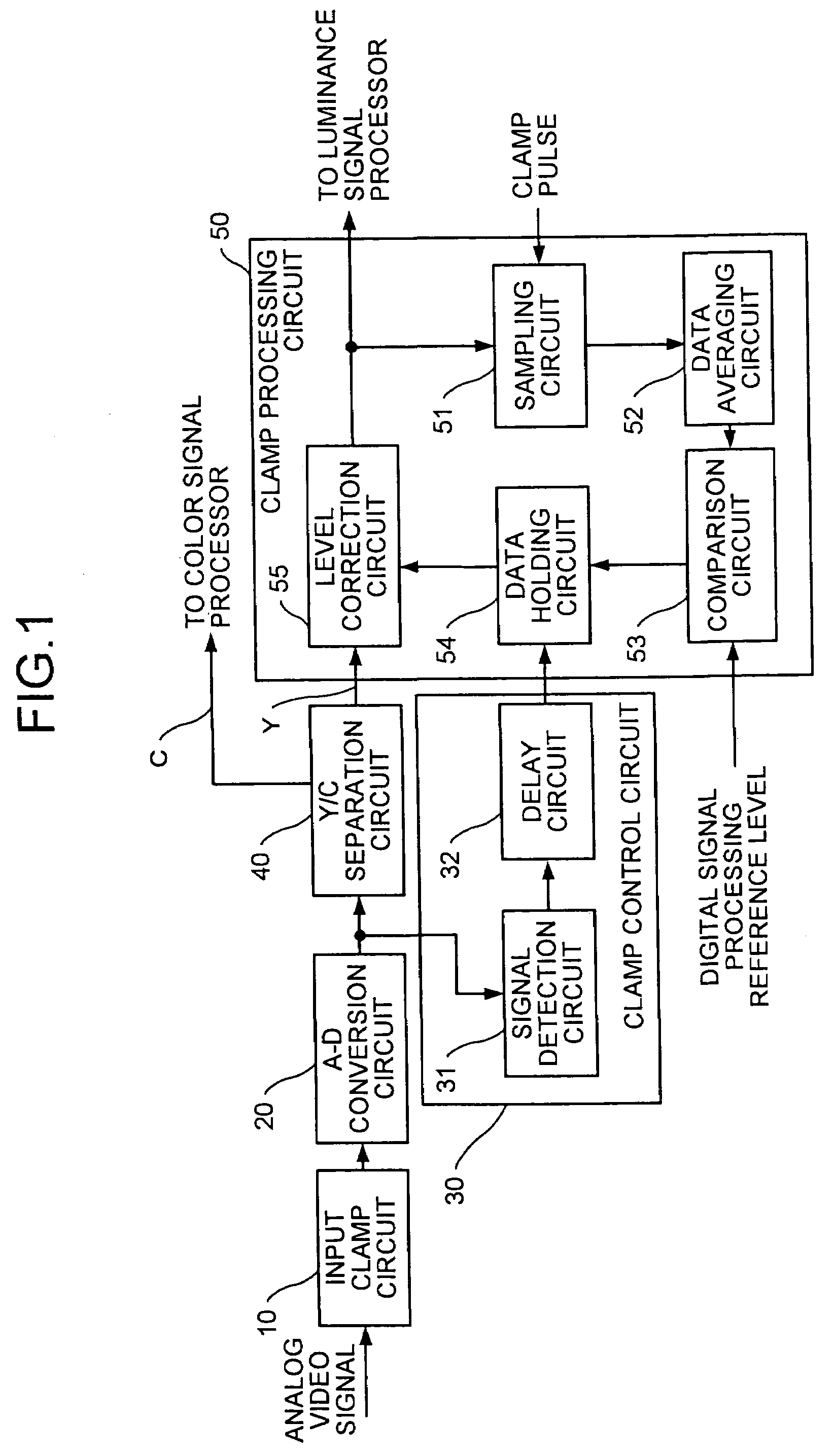
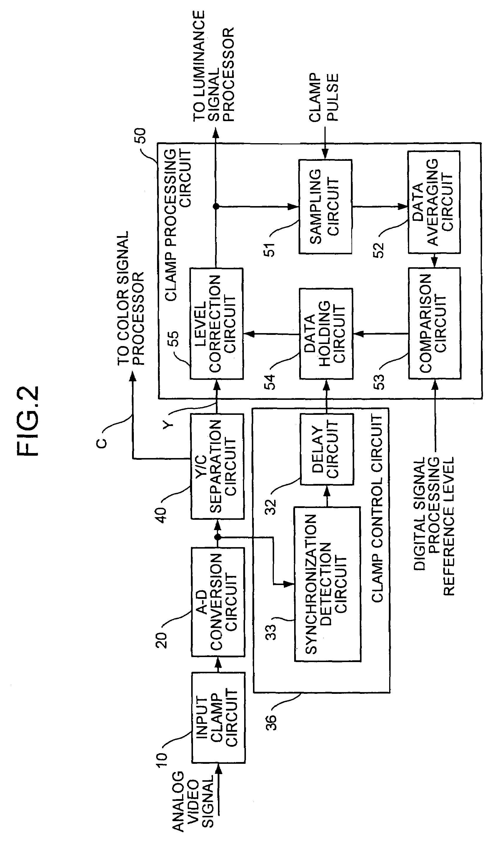
[0016]FIG. 1 is a block diagram of a clamp circuit according to one embodiment of the present invention. The clamp circuit of the present embodiment includes an input clamp circuit 10, an A-D conversion circuit 20, a clamp control circuit 30, a Y / C separation circuit 40, and a clamp processing circuit 50.

[0017]The input clamp circuit 10 clamps an analog video signal to a DC level that does not exceed a dynamic range of the A-D conversion circuit 20, and outputs the analog video signal clumped to the A-D conversion circuit 20.

[0018]The A-D conversion circuit 20 converts the analog video signal clamped by the input clamp circuit 10 to a digital video signal, and outputs the digital video signal obtained by the conversion to the Y / C separation circuit 40 and the clamp control circuit 30. The conversion time during which the A-D conv...


PUM


Abstract

A clamp control circuit outputs a clamp control signal after a delay of a predetermined time if a digital video signal is detected. A sampling circuit that extracts sampling data of a pedestal level from a luminance corrected signal based on a clamp pulse at a timing of the back porch. A data averaging circuit calculates an average of the sampling data of the pedestal level. A data holding circuit holds a difference between the average and a digital signal processing reference level when the clamp control signal is output and also when the clamp control signal is not output. A level correction circuit corrects a level of the luminance signal based on the difference held by the data holding circuit and outputs the corrected luminance signal.

Description

BACKGROUND OF THE INVENTION[0001]1) Field of the Invention[0002]The present invention relates to a clamp circuit that converts a video signal to a digital signal and conducts digital signal processing.[0003]2) Description of the Related Art[0004]The picture, quality of the television receiver sets is becoming better and better and the screen size is becoming large and larger day by day. To cope with this progress, there is a tendency to convert an analog video signal to a digital signal and perform some kind of digital signal processing to the digital signal. An analog-digital (A-D) converter is used to perform the conversion. During such conversion, the video signal is clamped in such a manner that the video signal does not exceed a dynamic range of the A-D converter.[0005]While the video signal travels through different components of the circuitry, until it reaches to a digital signal processing circuit, which performs the digital signal processing, a DC level of the video signal ...

Claims


Application Information

Patent Timeline
Patent Type & Authority Patents(United States)
IPC IPC(8): H04N5/04H04N5/16H04N5/18H04N5/57H03G11/00H03L5/00
CPCH04N5/18H03G11/00
Inventor TACHIBANA, MASANORI
Owner RENESAS ELECTRONICS CORP
Why Eureka
Try Eureka