Override assembly for door lock systems having a clutch mechanism

a technology of clutch mechanism and override assembly, which is applied in the field of door mounted security systems, can solve the problems of inoperable entry control devices, particularly electronic control entry devices, and mechanical control devices

Inactive Publication Date: 2006-08-29
HARROW PRODS
View PDF52 Cites 49 Cited by
  • Summary
  • Abstract
  • Description
  • Claims
  • Application Information

AI Technical Summary

Benefits of technology

[0004]In other constructions, an arcuate carriage cooperates with the engagement pin to move the engagement pin between the first position and the second position. A frame biases the carriage towards a third position, in which the frame maintains the engagement pin in the first position. A removable interchangeable core, when installed, blocks the frame moving the carriage toward the third position. The core, when removed, allows the frame to move the carriage toward the third position, resulting in movement of the engagement pin toward the first position and permitting retraction of the latch.

Problems solved by technology

In some cases, entry control devices, and particularly electronically controlled entry devices, are inoperable during power failures and / or when dedicated power sources fail.
Additionally, when electrical power is unavailable, conventional electronically controlled entry control devices generally remain in a locked position, restricting access through the door.

Method used


Image

  • Override assembly for door lock systems having a clutch mechanism
  • Override assembly for door lock systems having a clutch mechanism
  • Override assembly for door lock systems having a clutch mechanism

Examples


Embodiment Construction

[0016]The terms“first”, “second”, “upward”, “downward”, “horizontal”, and “vertical” are used herein and in the appended claims for description only and are not intended to imply any particular orientation, order, or importance.

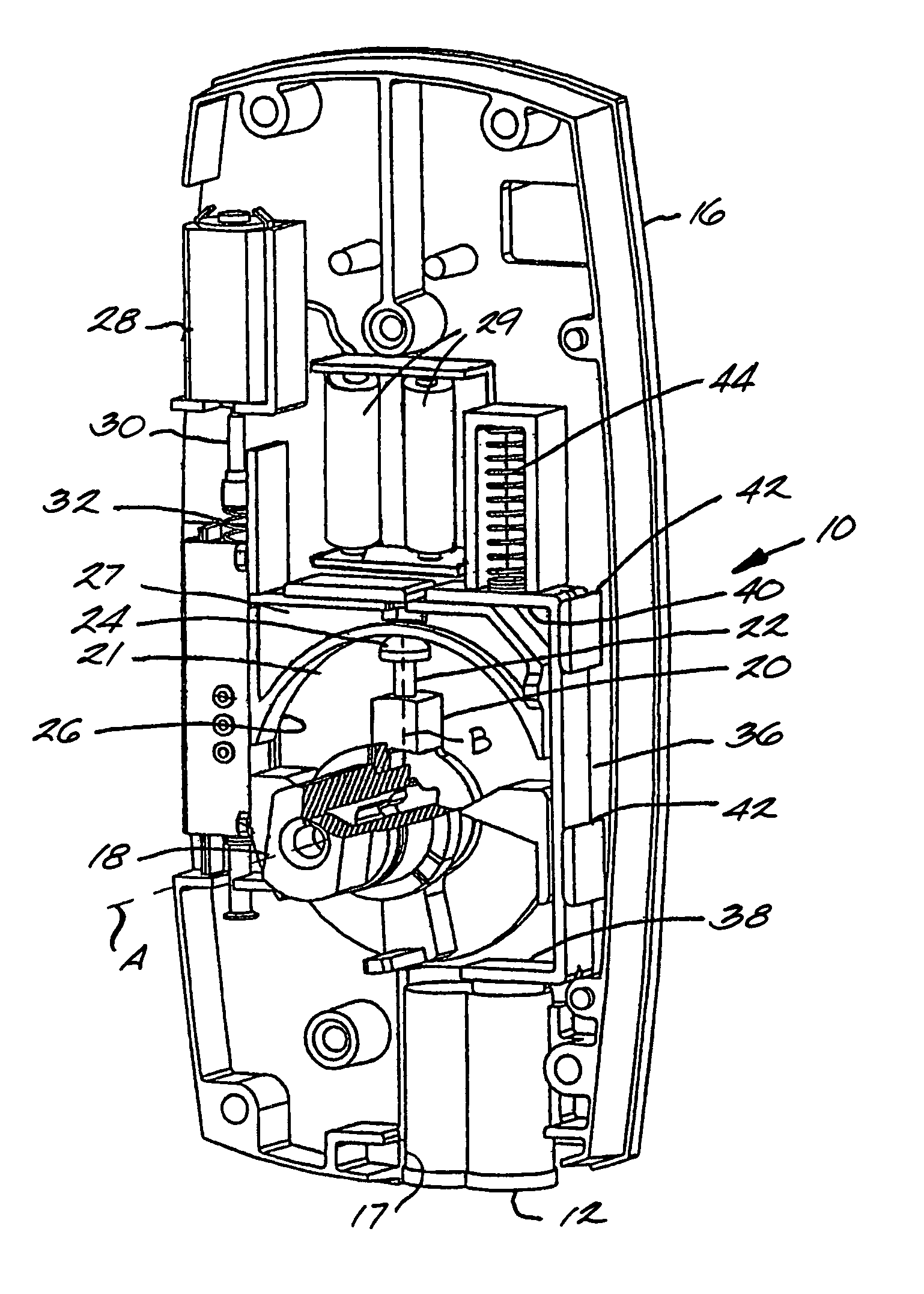
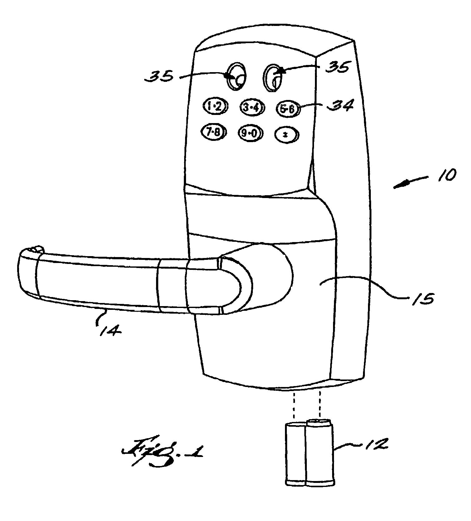
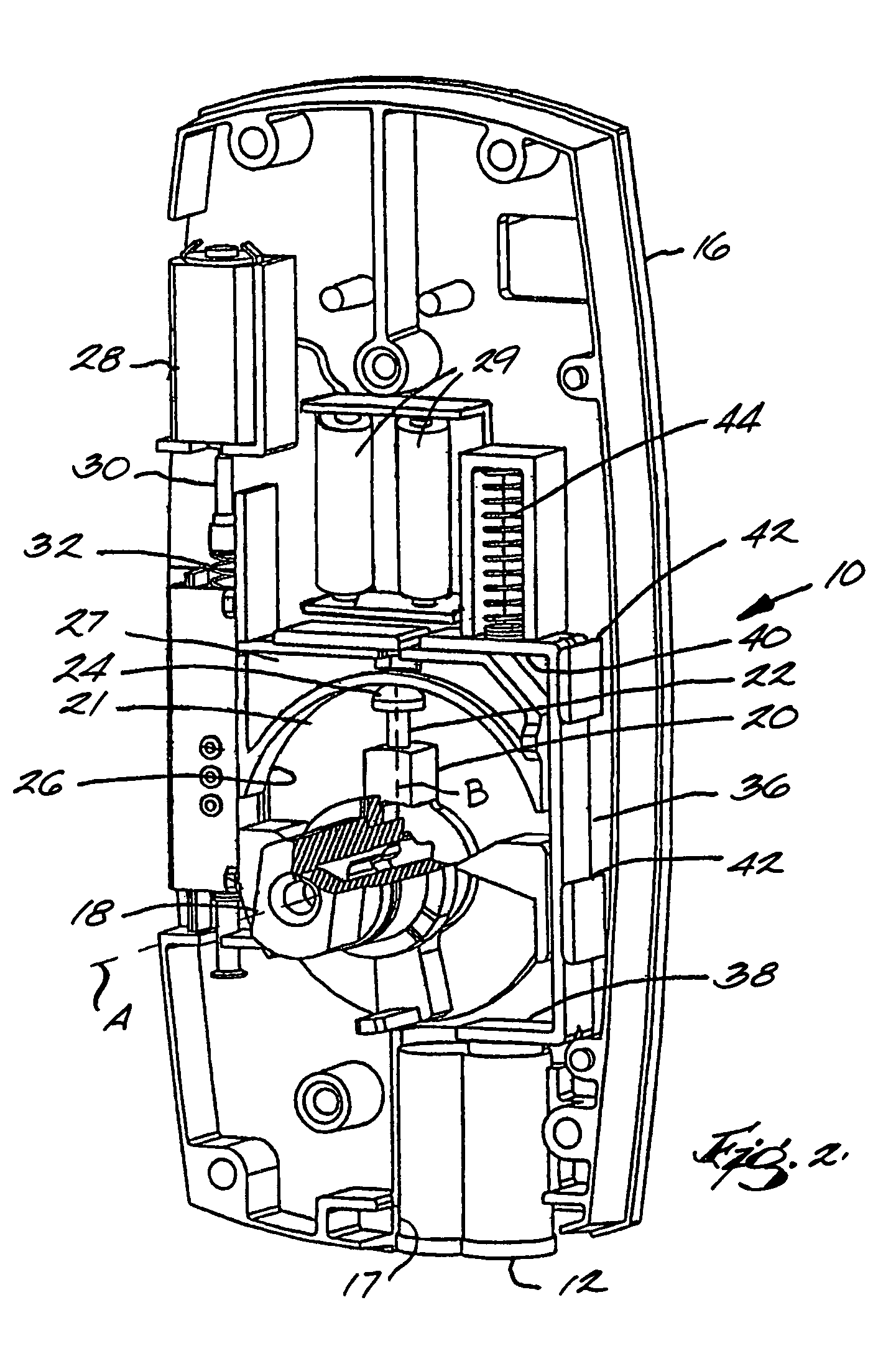
[0017]FIGS. 1–4 illustrate a lock system 10 according to a first construction of the present invention. The lock system 10 is mountable on an exterior side of a door (not shown) and is operable to limit access through the door and the associated doorframe (not shown). Also, in some constructions (not shown), the lock system 10 can be hardwired.

[0018]As described in greater detail below, the lock system 10 includes an electronically operated clutch mechanism having an override assembly. In some constructions of the present invention, some of the elements of the lock system 10 function in a manner that is similar to the apparatuses described in U.S. Pat. No. 6,286,347, issued Sep. 11, 2001, entitled “CLUTCH MECHANISM WITH MOVEABLE INJECTOR RETAINER WALL FOR DOO...


PUM


Abstract

A lock system for a door. The lock system includes a clutch mechanism and a lockset with a lockable latch and actuator for operating the latch. The clutch mechanism includes an input cam, an output cam, and an engagement pin having an axis and being dimensioned and configured for axial movement between a first position, in which the engagement pin engages both the input and output cams so that the input and output cams rotate synchronously, and a second position, which allows independent rotational movement of the input cam and the output cam.

Description

FIELD OF THE INVENTION[0001]The present invention relates generally to door mounted security systems and, more particularly, to a lock system that can be employed with entry control devices to control access through a door.BACKGROUND OF THE INVENTION[0002]Entry control devices are generally mounted on a door and / or a doorframe and operate to limit access through the door. Some conventional entry control devices include a clutch mechanism that selectively couples a bolt and a handle in response to an electronic input, which may be provided by a keypad, a contact activatable chip, a card reader, and other similar input devices. In some cases, entry control devices, and particularly electronically controlled entry devices, are inoperable during power failures and / or when dedicated power sources fail. Additionally, when electrical power is unavailable, conventional electronically controlled entry control devices generally remain in a locked position, restricting access through the door....

Claims


Application Information

Patent Timeline
Patent Type & Authority Patents(United States)
IPC IPC(8): E05B55/04E05B47/00E05B47/06
CPCE05B47/0012E05B47/0692E05B2047/0031E05B2047/0016E05B2047/0023E05B63/0069Y10T70/713Y10T70/5496Y10T70/5416Y10T70/7062Y10T70/5823
Inventor WALSH, III, JOHN E.NGUYEN, VU DINH
Owner HARROW PRODS
Why Eureka
Try Eureka