Incandescent light power controller with predetermined off-state impedance

a technology of incandescent light and power controller, which is applied in the direction of lighting apparatus, instruments, light sources, etc., can solve the problems of non-linear dimming, limiting their use, and instability and other anomalous operations, and achieves no erratic behavior

Inactive Publication Date: 2006-08-29
LONGLITE
View PDF6 Cites 10 Cited by
  • Summary
  • Abstract
  • Description
  • Claims
  • Application Information

AI Technical Summary

Benefits of technology

[0016]The limitations of the known prior art are addressed in the present invention. The present invention provides apparatus and methodology wherein a lamp with a co-located life extending semi-conductor switch, used with an adjustable commonplace dimmer, exhibits no erratic behavior. Note the terms “switch” and “switch device” are used interchangeably herein. The charging of the timing capacitor in the dimmer operates substantially as if there were no co-located device present. The present invention provides for the principal series resistance through which the capacitor is charged to be the timing resistance in the dimmer. This ensures that the dimmer operates normally.

Problems solved by technology

Rheostat dimmers generated substantial heat, limiting their use.
Typically these built-in electronic devices perform as life-extending devices rather than as lamp dimmers since these electronic devices are not easily accessible.
In such a situation undesirable interaction, instability and other anomalous operations can occur due to these two circuits.
Typically, flicker, erratic, and non-linear dimming occurs.
In such a condition, the timing capacitor in the wall-mounted dimmer may take more than a few AC line half cycles to charge, thereby upsetting the normal discharge / reset mechanism in the dimmer.
Such disruption of the normal discharge / charge mechanism can result erratic light behavior, like visible flickering and diminished range of dimming control.
However, in the above mentioned case where a wall-mounted dimmer and a life extending semi-conductor device are combined in series with the bulb filament, the capacitor will not charge in the normal fashion.
The off life extending semiconductor will cause erratic operation of the combination.

Method used


Image

  • Incandescent light power controller with predetermined off-state impedance
  • Incandescent light power controller with predetermined off-state impedance
  • Incandescent light power controller with predetermined off-state impedance

Examples


Embodiment Construction

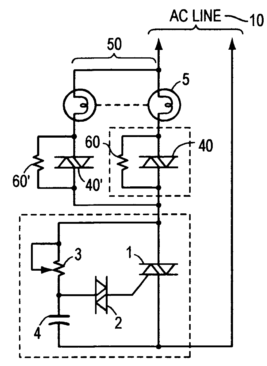
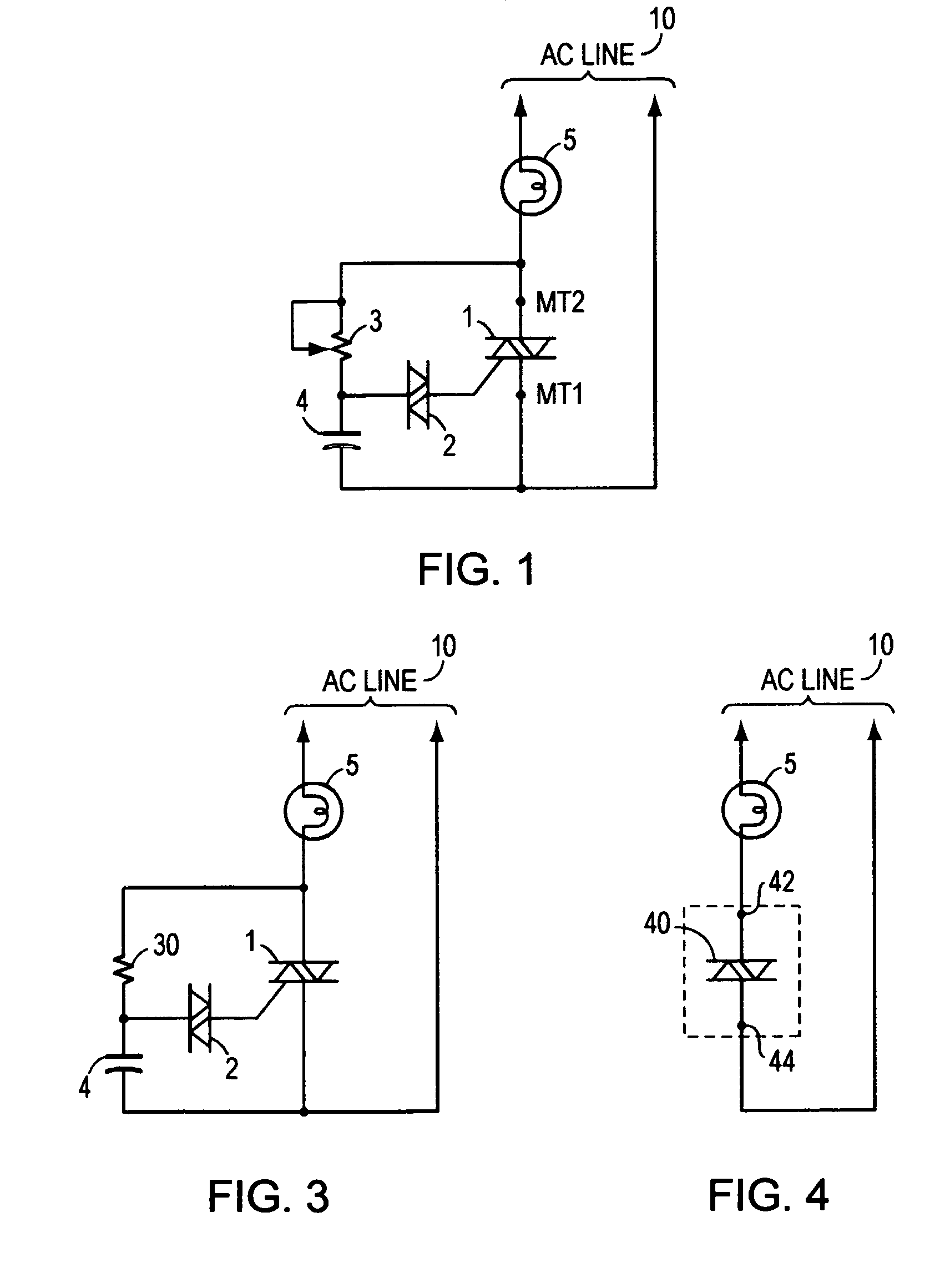
[0045]In FIG. 1, the circuit consists of triac 1, diac 2, variable resistor (i.e. potentiometer) 3 capacitor 4 and incandescent lamp and filament 5. The triac is a three terminal device, having two terminals, MT1 and MT2, which act as the two terminals of an on / off switch. The diac is a bilaterial switching device which switches from off to on (with a voltage offset) when a suitable voltage is impressed across its two terminals. The capacitor charges up via items 3 and 5 to a voltage level that triggers of the diac.

[0046]At the beginning of each half cycle of the AC line voltage, the capacitor 4 begins to charge toward a voltage level corresponding to the specified breakover threshold of diac 2. The diac switches from an off state to a condition of conduction substantially discharging the capacitor 4.

[0047]The discharge path for the capacitor is through the diac and the internal triac impedance between MT1 and the gate terminal G. When the diac gconducts, sufficient voltage is impre...


PUM


Abstract

An incandescent light bulb life extender circuit is designed to attach to the screw base of a conventional light bulb or incorporated in series with the AC powering the bulb. The circuit employs a bidirectional semiconductor switch that reduces the brightness of the bulb marginally while significantly extending the bulb's life. The values of the life extender are selected to operate with standard available light dimmers with no undesirable flicker or compromise of reasonable brightness control. A controller consists of the life extending circuit and a) an appropriate molded insulating housing, b) electrically conductive metallic discs for making electrical contacts to a light bulb base and corresponding socket and c) selected electronic components, connected to said discs, to facilitate the intended electrical performance.

Description

CROSS REFERENCE TO RELATED APPLICATIONS[0001]The present application claims the priority benefit of an earlier filed provisional application of common inventorship. This provisional application has Ser. No. 60 / 591,675 and was filed on Jul. 28, 2004, and this provisional application is hereby incorporated herein by reference.FIELD OF THE INVENTION[0002]The present invention relates to control of incandescent bulbs or lamps, and more particularly to control of single or multiple bulbs with co-located electronics. Co-located defined herein as being built into or attached to the bulb itself or into the bulb mounting socket.BACKGROUND OF THE INVENTION[0003]The basic incandescent light bulb dimmer has existed as a commercial product for over 40 years (hereinafter lamp and light bulb are used interchangeably). The lamp dimmer became practical with the development of a class of semiconductor solid state switch devices known as thyristors that were introduced to the electronics markets in th...

Claims


Application Information

Patent Timeline
Patent Type & Authority Patents(United States)
IPC IPC(8): H05B37/00
CPCH05B39/08H05B39/00
Inventor RODRIGUEZ, EDWARD T.
Owner LONGLITE
Why Eureka
Try Eureka