Method and apparatus for motion adaptive deinterlacing

a technology motion, applied in the field of motion adaptive deinterlacing, can solve the problems of loss of vertical detail, information shortfall during format conversion, abhorrent visual quality, etc., and achieve the effect of improving feathering detection

Inactive Publication Date: 2006-08-29
JALDI SEMICON CORP
View PDF28 Cites 57 Cited by
  • Summary
  • Abstract
  • Description
  • Claims
  • Application Information

AI Technical Summary

Benefits of technology

[0017]In accordance with a further aspect of the invention, there is provided a feathering detector for detecting a feathering artifact in adjacent odd and even fields about a target pixel. The feathering detector comprises a contour selector, a difference calculator and a plurality of predefined thresholds. The contour selector selects from a plurality of contours, including non-linear contours. The difference calculator calculates a plurality of differences between pixels along the selected contour. The plurality of predefined thresholds are compared with the calculated differences for determining if feathering exists about the pixel. Including non-linear contours among the contour selection improves feathering detection in arbitrary shapes.

Problems solved by technology

Despite the apparent reconstruction, displaying interlaced video signals has several drawbacks, which include introducing artifacts associated with interlaced signals.
Thus, there is an information shortfall during format conversion.
The format conversion challenge is that of reconstructing the entire image scene at an instant in time, even though only half of it is available at that time.
An obvious problem with this approach is an abhorrent visual quality that results when motion is present in the image scene.
The line doubling method has several drawbacks, one of which is the complete discounting of relevant image scene information in a previous field.
Line doubling can lead to flicker and to a loss of vertical detail.
Such strategies often depend upon vast computational resources to operate effectively, and even then, mismatching errors can result.
Mismatches can be perceptually dissatisfying to a viewer, especially when a portion of the image content is placed in the wrong part of the target image.
Such a system still requires huge computational power.
Furthermore, research has shown that adjusting the filters based solely on motion information results in blotchy processed sequences.
However, these methods cannot scale and deinterlace simultaneously.
Nor do they deal that effectively with the artifacts inherent in interlaced images, namely flicker, stair-stepping and especially artifacts that are motion-related such as feathering.

Method used


Image

  • Method and apparatus for motion adaptive deinterlacing
  • Method and apparatus for motion adaptive deinterlacing
  • Method and apparatus for motion adaptive deinterlacing

Examples


Embodiment Construction

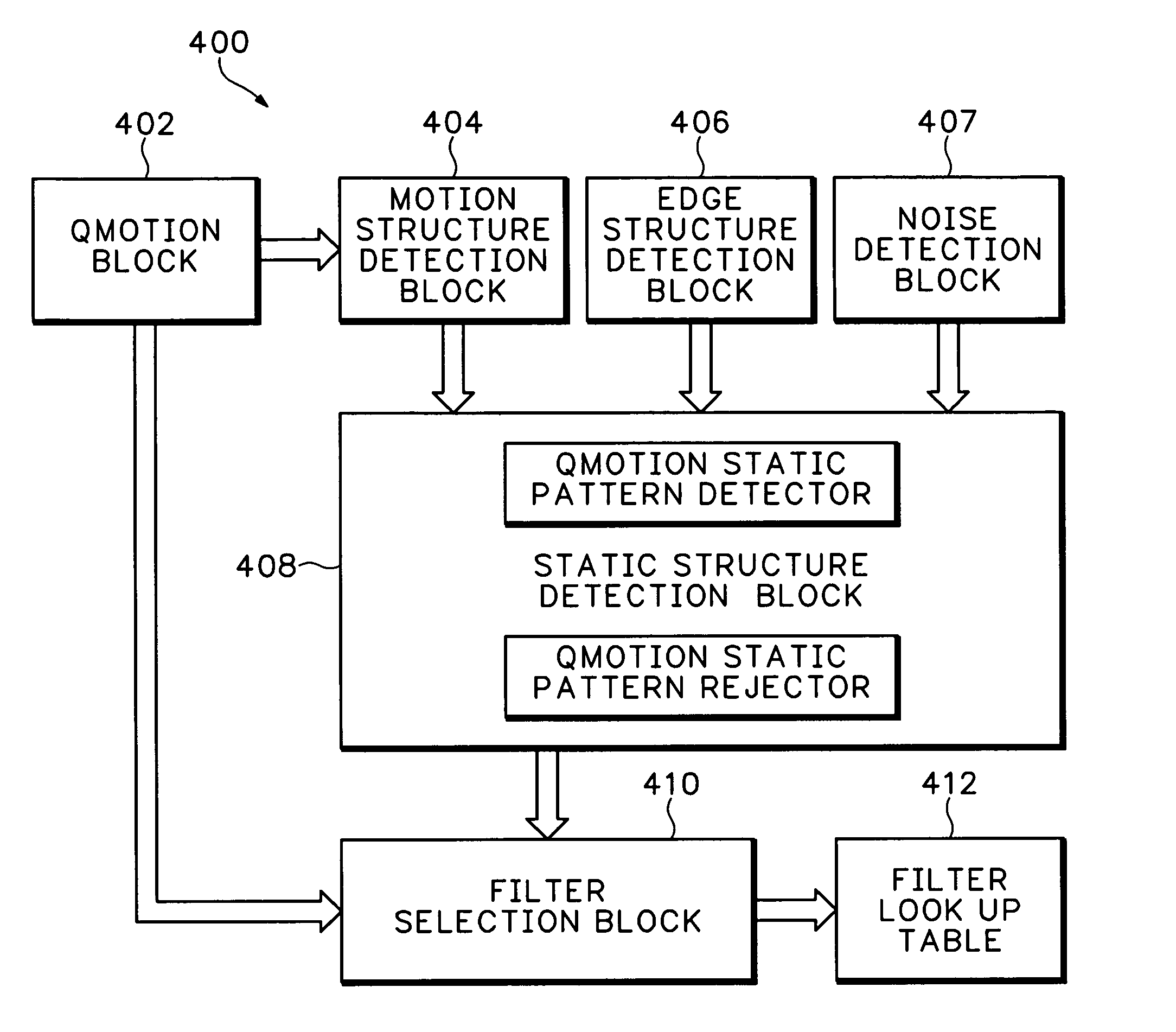
[0037]The following description can be applied to a method of format conversion for interlaced-to-progressive scan conversion (deinterlacing) and a method of interlaced-to-interlaced conversion (reinterlacing) that simultaneously scales and deinterlaces or scales and reinterlaces. The latter is a requirement for format conversion where the source image format and the target image format are not necessarily the same. The methodology used is based on what will be referred to as motion-adaptive vertical-temporal (MAVT) filtering.

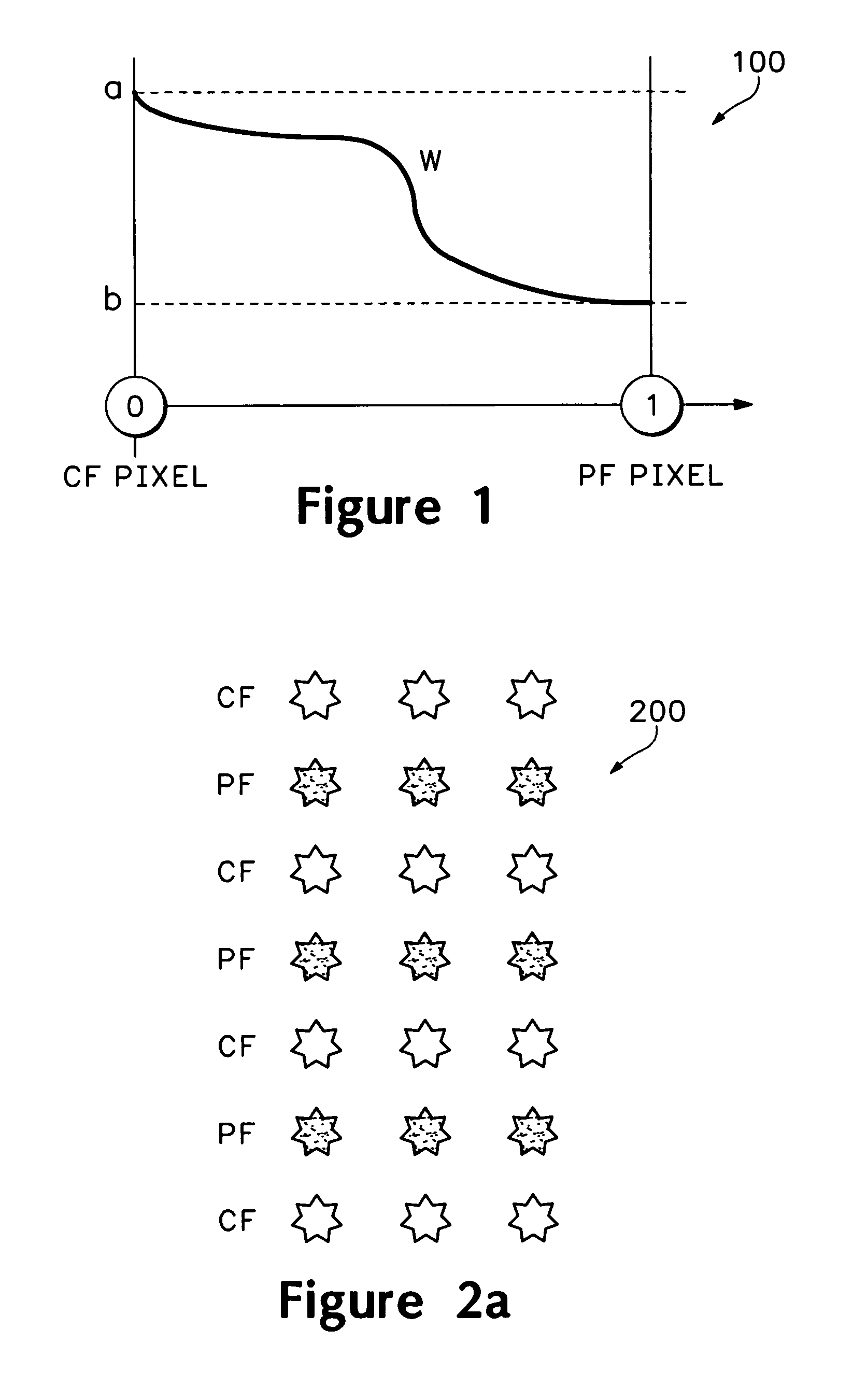
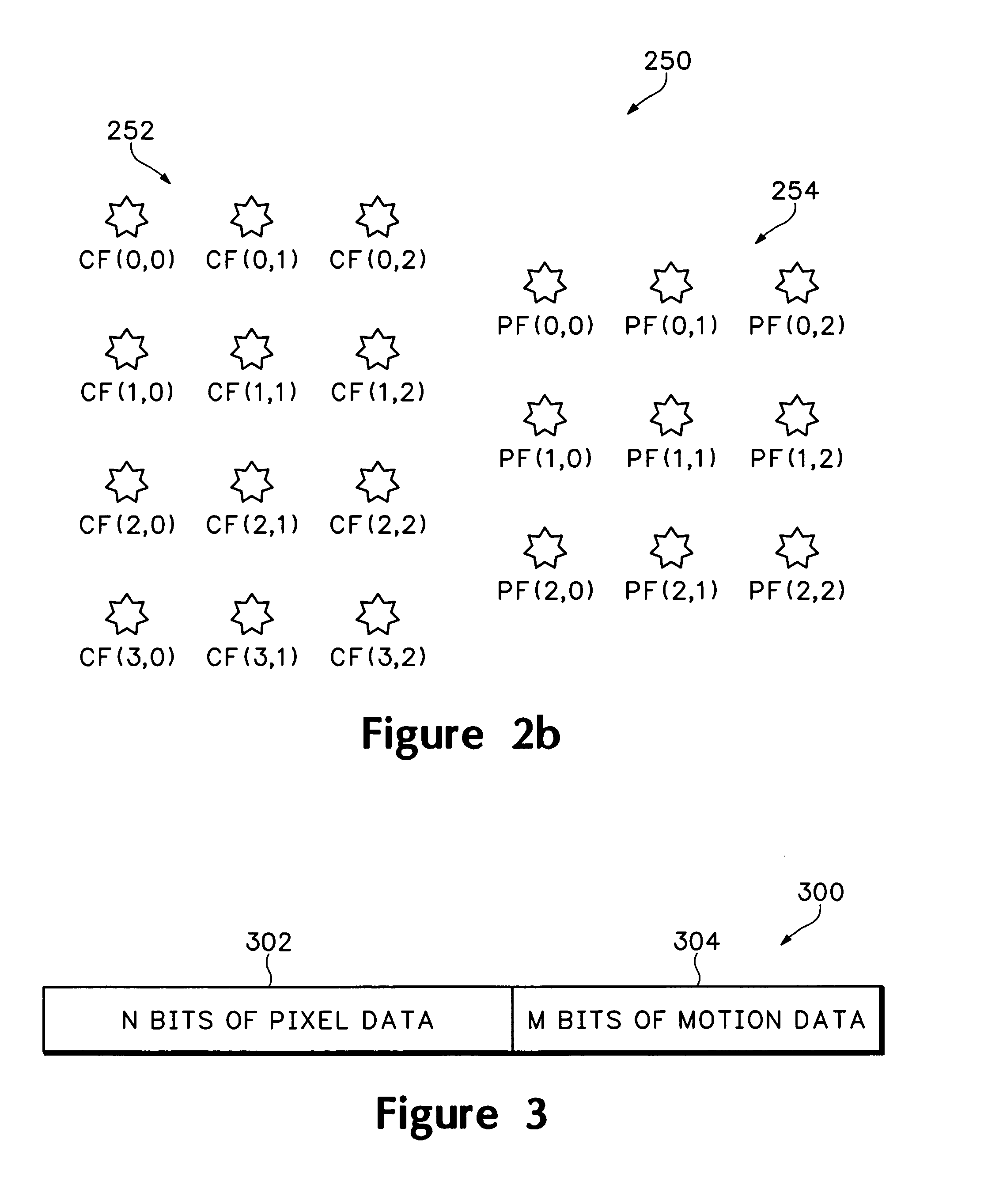
[0038]MAVT filtering uses inter-field interpolation to compute a target pixel value. That is, image pixel data is combined from both the current field (CF) and the previous field (PF) to compute the target pixel. In addition, information derived from several past fields is used to assist the decision making process.

[0039]The MAVT filtering approach described herein emphasizes either the CF pixel data or the PF pixel data, depending on the degree of estimated in...


PUM


Abstract

An adaptive filter calculates a target pixel from an interlaced video signal. The video signal comprises a plurality of frames, each of which comprises an even and an odd field. The filter comprises a quantized motion calculator and a filter selector. The quantized motion calculator estimates an amount of motion about the target pixel. The filter selector selects a filter in accordance with the estimated amount of motion. The filter applies a first weighting factor to a plurality of current field pixels and a second weighting factor to a plurality of previous field pixels for creating the target pixel.

Description

[0001]This application is a continuation of U.S. patent application Ser. No. 09 / 948,721, filed Sep. 10, 2001 now U.S. Pat. No. 6,757,022, and is herein incorporated by reference.[0002]The present invention relates generally to a video format conversion system, and in particular to a video format conversion system for converting interlaced video to progressive video and interlaced video to interlaced video of a different size.BACKGROUND OF THE INVENTION[0003]Interlaced signals are generated from a line-by-line scan of an image scene. The signals are generated by scanning and transmitting every other line of the image scene. In this way, even lines of the image scene are scanned and transmitted and then odd lines are scanned and transmitted. The even and odd lines in the image scene are referred to as the even field and the odd field, respectively. A time delay between the image scene capture of the even and odd fields is approximately one sixtieth of a second. A combination of the ev...

Claims


Application Information

Patent Timeline
Patent Type & Authority Patents(United States)
IPC IPC(8): H04N7/01H04N11/20H04N5/14H04N5/44
CPCH04N5/142H04N5/144H04N7/012H04N19/117H04N19/139H04N19/51H04N7/0137H04N7/0115H04N7/0142
Inventor WREDENHAGEN, G. FINNCHENG, GARYJANG, SOO CHANGGREGGAIN, LANCE
Owner JALDI SEMICON CORP
Why Eureka
Try Eureka