Image forming apparatus with guide member guiding image forming medium
a technology of image forming apparatus and guide member, which is applied in the direction of electrographic process apparatus, thin material processing, instruments, etc., can solve the problems of image quality degradation and problems experienced in the final print, and achieve the effects of preventing toner, favorable image quality, and free from noise and contamination
- Summary
- Abstract
- Description
- Claims
- Application Information
AI Technical Summary
Benefits of technology
Problems solved by technology
Method used
Image
Examples
first embodiment
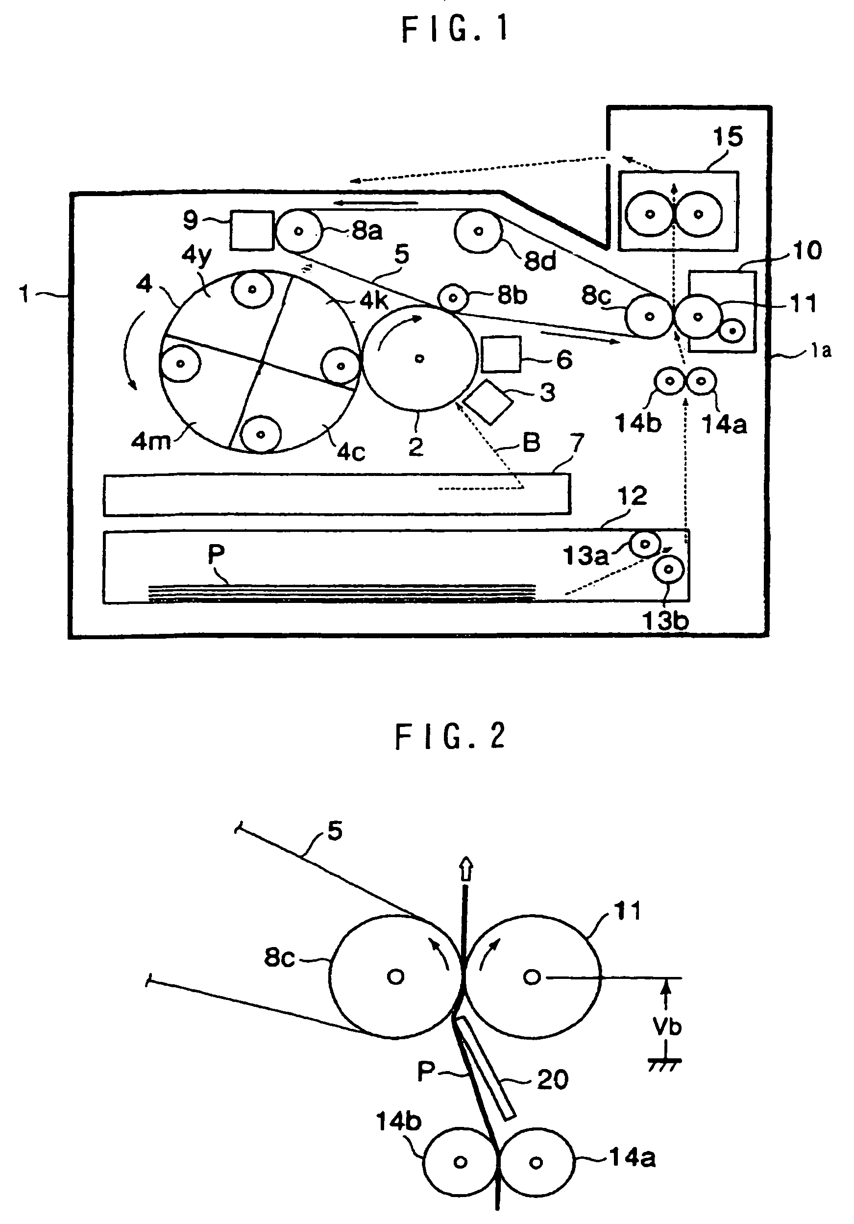
[0022]FIG. 1 shows the arrangement of a color image forming apparatus, i.e. a color printer, using an electrophotographic process. The color printer has a body 1 with a frame 1a. A photosensitive drum 2 serving as an image carrier is provided approximately in the center of the frame 1a. A charging unit 3, a color developing unit 4, a transfer belt 5 as an intermediate transfer medium, and a destaticizer / cleaner 6 are positioned around the photosensitive drum 2.
[0023]The charging unit 3 applies a high-level bias voltage to the photosensitive drum 2, thereby electrostatically charging the surface of the photosensitive drum 2. The charged surface of the photosensitive drum 2 is irradiated with a laser beam B from an optical system unit 7. The laser beam B scans the surface of the photosensitive drum 2 in one direction to effect horizontal scanning (line scanning). The horizontal scanning is repeated as the photosensitive drum 2 rotates, thereby effecting vertical scanning. In this way,...
second embodiment
[0047]A second embodiment of the present invention will be described below.
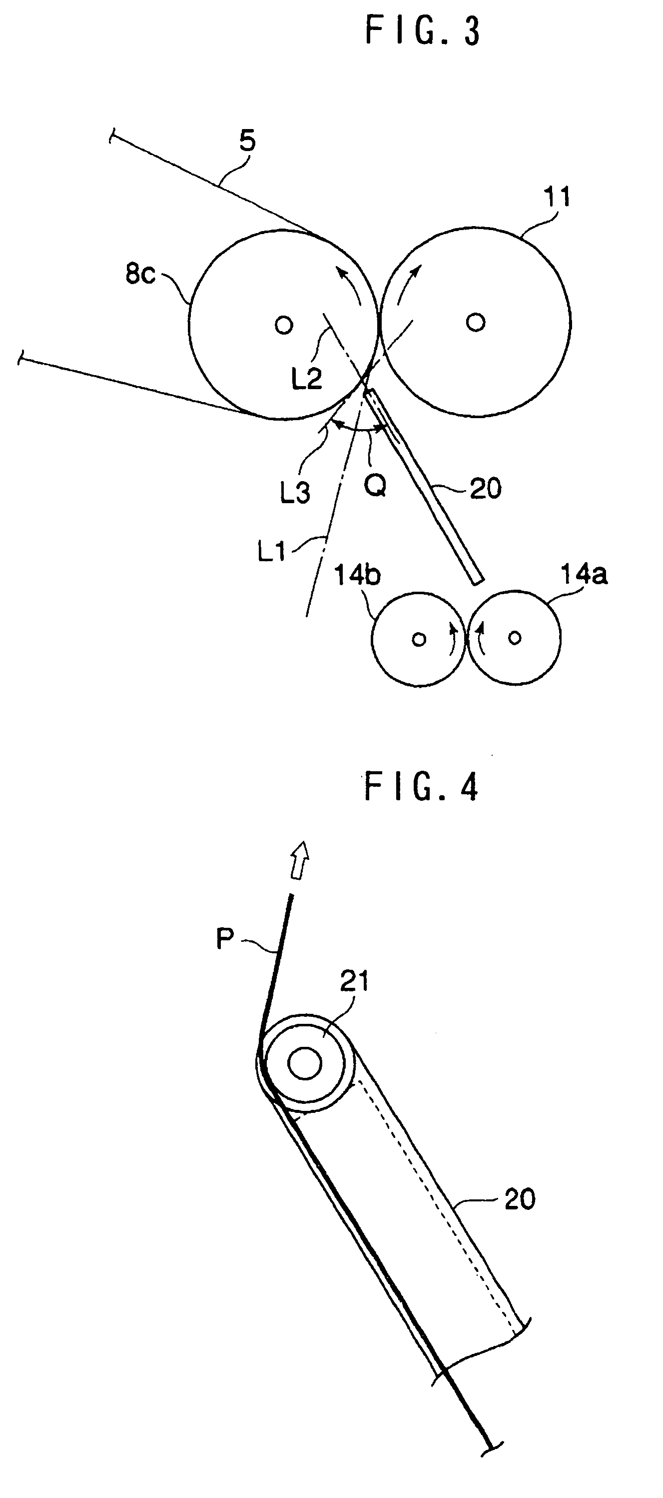
[0048]As shown in FIG. 4, a roller 21 is provided at the upper end of the guide member 20 (i.e. an end thereof closer to the transfer belt 5). The roller 21 rotates in response to the movement of the sheet P.
[0049]The roller 21 minimizes friction occurring between the upper end edge of the guide member 20 and the sheet P and allows the sheet P to move smoothly. It is also possible to avoid damage to the sheet P.
[0050]The rest of the arrangement of the second embodiment and the operation thereof are the same as in the first embodiment.
third embodiment
[0051]A third embodiment of the present invention will be described below.
[0052]As shown in FIGS. 5 and 6, the guide member 20 is pivotably supported at an intermediate portion thereof by a support member 22. A spring 23 is connected to the guide member 20 at a position above the support member 22 (i.e. closer to the transfer belt 5). The spring 23 applies biasing force to the guide member 20 toward the secondary transfer roller 11.
[0053]A stopper 24 is provided in the neighborhood of the secondary transfer roller 11 to limit the movement of the guide member 20 by the biasing force of the spring 23. In a state where the upper end portion of the guide member 20 abuts on the stopper 24 as shown in FIG. 5, the guide member 20 is in the same position as the guide member 20 in the first embodiment.
[0054]The lower end portion of the guide member 20 (i.e. an end portion closer to the regist roller 14a) is connected to a plunger 26 through a rod 25. The rod 25 and the plunger 26, together w...
PUM
 Abstract
Description
Claims
Application Information
 - R&D
- Intellectual Property
- Life Sciences
- Materials
- Tech Scout
- Unparalleled Data Quality
- Higher Quality Content
- 60% Fewer Hallucinations
Browse by: Latest US Patents, China's latest patents, Technical Efficacy Thesaurus, Application Domain, Technology Topic, Popular Technical Reports.
© 2025 PatSnap. All rights reserved.Legal|Privacy policy|Modern Slavery Act Transparency Statement|Sitemap|About US| Contact US: help@patsnap.com


