Pulse tube refrigerator

a refrigerator and pulse tube technology, applied in refrigeration machines, gas cycle refrigeration machines, lighting and heating apparatus, etc., can solve the problems of unsuitable actual use, rather small resonator tubes of former arts with inevitably large heat-driven pressure-wave generators, and unsuitable for small-size resonator tubes. , to achieve the effect of reducing vibration, reducing vibration, and free from vibration and nois

Inactive Publication Date: 2006-12-14
JAPAN AEROSPACE EXPLORATION AGENCY +1
View PDF11 Cites 15 Cited by
  • Summary
  • Abstract
  • Description
  • Claims
  • Application Information

AI Technical Summary

Benefits of technology

[0012] In order to solve the above mentioned problems, the present invention has configuration of a pulse-tube refrigerator comprising a pulse tube, a cool storage unit connected to the low-temperature side of the pulse tube, a vibration generator connected to the high-temperature side of the cool storage unit, and a reservoir with an orifice connected to the high-temperature side of the pulse tube, and said vibration generator consists of a heat-driven tube equipped with a heat-storage unit, a heating heat exchanger, a radiation heat exchanger, and a work transmission tube, of a phase shifter connected to an outlet portion of the heat-driven tube, and of a heat-driven pressure-wave generator equipped with a return path to connect the other portion of the phase shifter and the inlet end of the heat-driven tube. The configuration of the present invention enabled to implement a compact pulse-tube refrigerator free from vibration and noise. In other words, applying a solid displacer for the resonator and the phase shifter of the vibration generator and disposing them in facing opposite made the device compact and reduced vibration. The heat-driven pressure-wave generator with a resonator tube by the former arts was inevitably large since a small-size resonator does not resonate. A rather small-size resonator tube of former arts presented very low efficiency from the friction between the operation gas and the surface of the tube and was not suitable for actual use. By using a resonator and a phase shifter of the solid displacer, a compact and efficient heat-driven pressure-wave generator can be implemented. From the similar reason, arranging a resonator and a phase shifter of the solid displacer at the heat-absorber side enables to implement a compact and efficient pulse-tube refrigerator.

Problems solved by technology

The heat-driven pressure-wave generator with a resonator tube by the former arts was inevitably large since a small-size resonator does not resonate.
A rather small-size resonator tube of former arts presented very low efficiency from the friction between the operation gas and the surface of the tube and was not suitable for actual use.

Method used


Image

  • Pulse tube refrigerator
  • Pulse tube refrigerator
  • Pulse tube refrigerator

Examples


first embodiment

the Present Invention

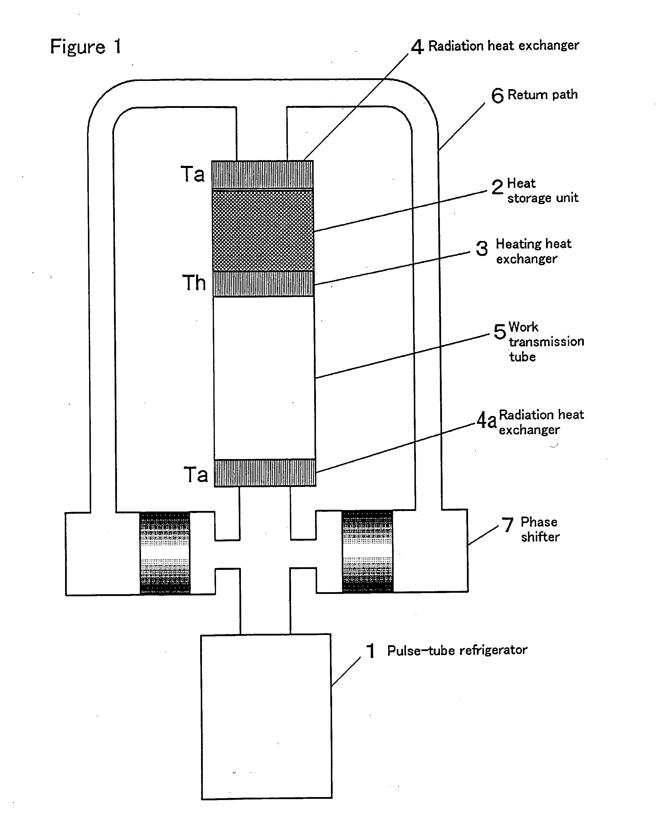
[0025] The first embodiment of the present invention is a pulse-tube refrigerator driven by a heat-driven pressure-wave generator equipped with a heat-driven tube, a phase shifter, and a return path.

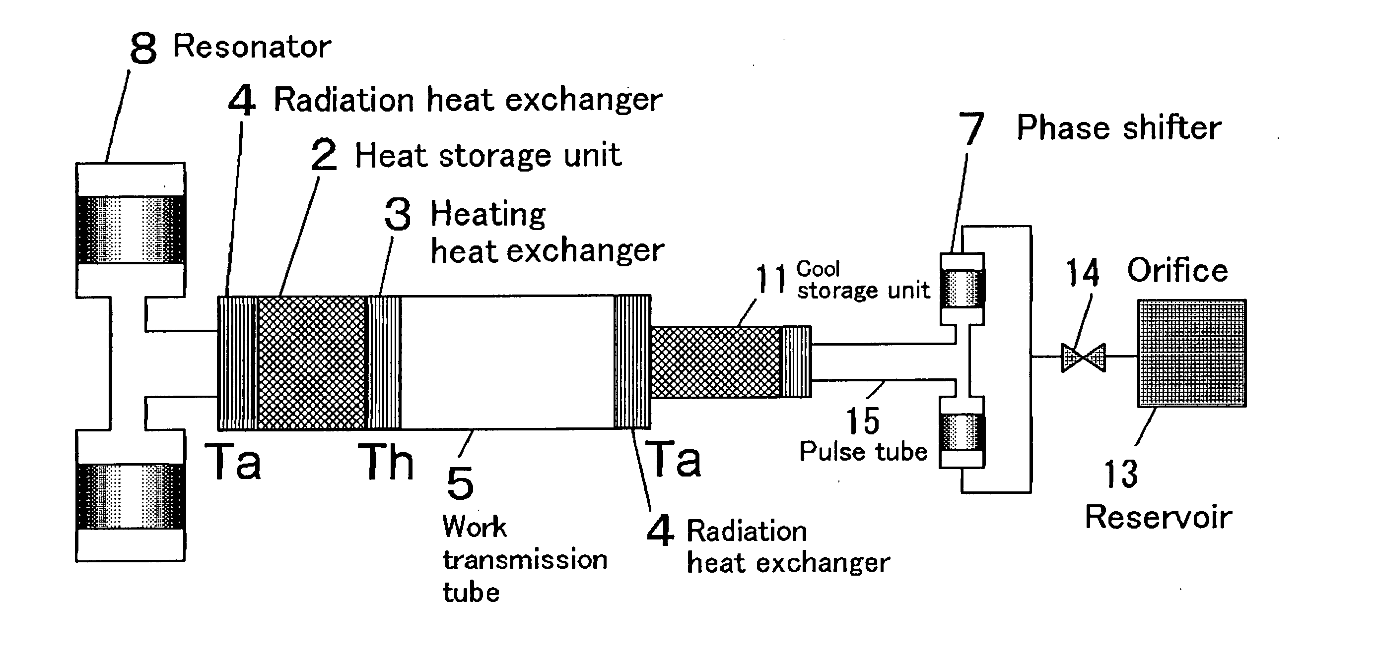
[0026]FIG. 1 shows the schematic diagram for the pulse-tube refrigerator in the first embodiment of the present invention, wherein the pulse-tube refrigerator 1 is an orifice-type pulse-tube refrigerator that has a pulse tube, a cool storage unit connected to the low-temperature side of the pulse tube, a vibration generator connected to the high-temperature side of the cool storage unit, and a reservoir with the orifice connected to the high-temperature side of the pulse tube. Although omitted in the figure, these are the same as in FIG. 10. The heat storage unit 2 is a means to form an isothermal space that has a constant thermal slope, which is called “regenerator”. The heating heat exchanger 3 is a means to supply heat to the high-temperature side of the heat sto...

second embodiment

the Present Invention

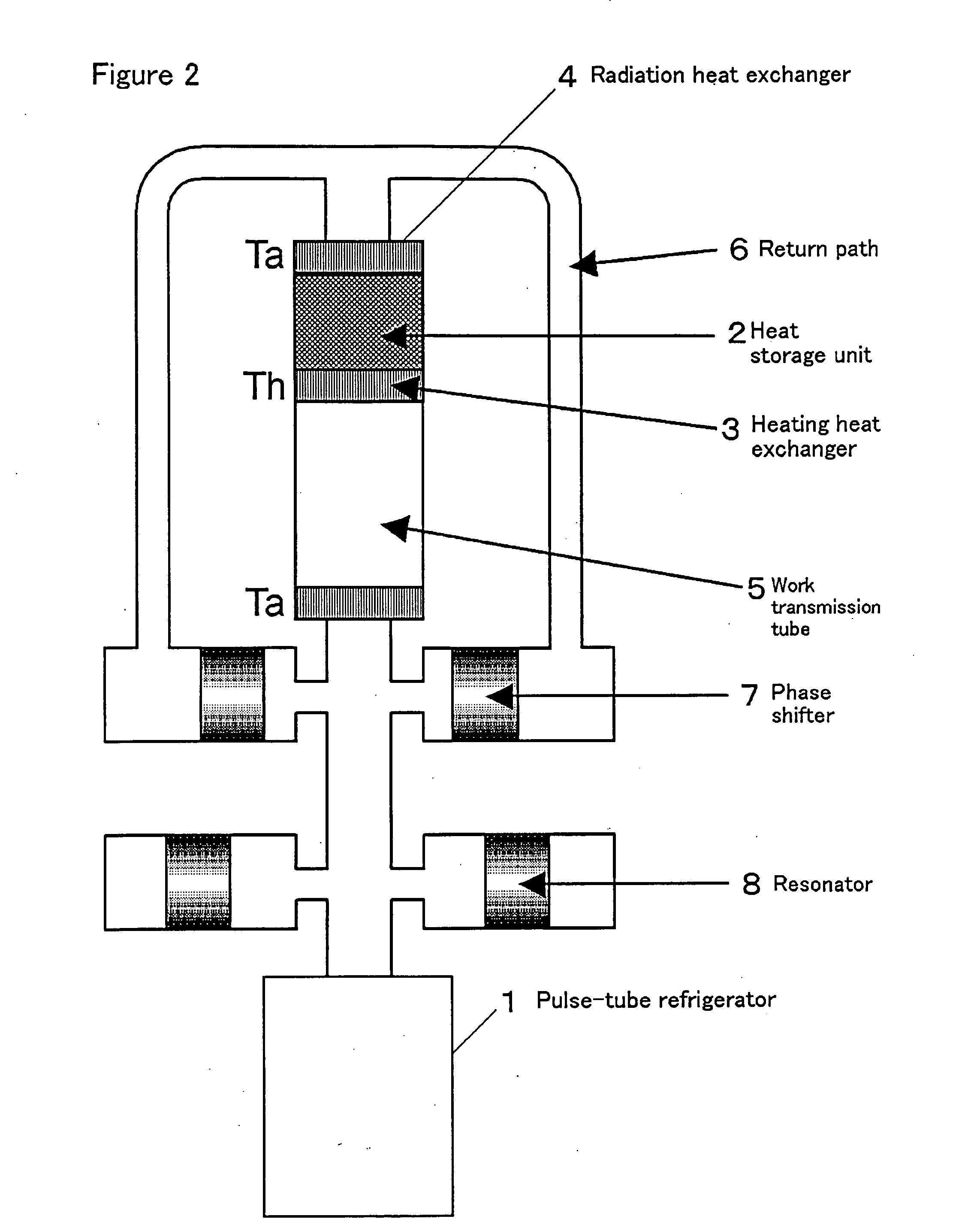
[0031] The second embodiment of the present invention is a pulse-tube refrigerator driven by a heat-driven pressure-wave generator that is equipped with a heat-driven tube, a resonator, a phase shifter, and a return path. The heat-driven pressure-wave generator is a Stirling-engine type. FIG. 2 shows a diagram of the pulse-tube refrigerator in the second embodiment of the present invention. In FIG. 2, the resonator 8 is a gas-spring resonator disposed at the work-output side of the heat-driven tube. The rest of the configuration is the same as in the first embodiment of the present invention. The basic configuration of this pulse-tube refrigerator is the same as the pulse-tube refrigerator in the former arts shown in FIG. 11. The significant difference is that the piston in the phase shifter can freely reciprocate. The heat-driven pressure-wave generator consists of the heat-driven tube, the return path 6, the phase shifter 7, and the resonator 8.

[0032] Here is...

third embodiment

the Present Invention

[0035] The third embodiment of the present invention is a pulse-tube refrigerator driven by a heat-driven pressure-wave generator that is equipped with a heat-driven tube and a resonator. The heat-driven pressure-wave generator is a standing-wave type. FIG. 3 is a schematic diagram that shows the configuration of the pulse-tube refrigerator in the third embodiment of the present invention. In FIG. 3, a heat storage unit 2 is a means to form an isothermal space that has a constant thermal slope. A heating heat exchanger 3 is a means to supply heat to the high-temperature side of the heat storage unit 2. A radiation heat exchanger 4 is a means to cool the low-temperature side of the heat storage unit 2 down to an ambient temperature. A high-temperature buffer 16 is a tube where the pressure wave is reflected to excite the standing wave in the heat-driven tube. The heat-driven tube consists of the heat storage unit 2, the heating heat exchanger 3, the radiation hea...


PUM


Abstract

A pulse tube refrigerator that is small in size and free from vibration and electric noise. A pulse tube refrigerator (1) has a pulse tube, a cool storage unit connected to the low-temperature side of the pulse tube, a vibration generator connected to the high-temperature side of the cool storage unit, and a reservoir with an orifice, connected to the high-temperature side of the pulse tube. The vibration generator is a thermally driven pressure wave generator having thermal drive tubes (heat exchangers (4-4a) for heat radiation), a phase shifter (7), and a return path (6). Sufficiently heating a heat exchanger (3) for heating causes self-exciting vibration to be generated in a work transmission tube (5), and work is returned to the thermal drive tubes through the phase shifter (7) and the return path (6) arranged on the work output side of the work transmission tube (5). The work is amplified by the thermal drive tubes, and is then outputted from the work transmission tube (5) and fed to the pulse tube refrigerator (1). A vibration generator for a pulse tube refrigerator that is small in size and free from vibration and noise can be realized.

Description

FIELD OF THE INVENTION [0001] The present invention relates to a pulse-tube refrigerator, especially to the pulse-tube refrigerator equipped with a pressure-vibration generator that generates pressure vibration by heat. BACKGROUND OF THE INVENTION [0002] A pulse-tube refrigerator consists of a pulse tube, a cool storage unit connected to the low-temperature side of the pulse tube, and a compressor connected to the high-temperature side of the cool storage unit. The pulse-tube refrigerator dispenses with moving parts at the low-temperature side. A pulse-tube refrigerator with a motor-driven compressor generates pressure vibration in the pulse tube by switching open and close alternately a pair of high-pressure and low-pressure valves that are settled between the compressor and the cool storage unit. The basic-type pulse-tube refrigerator by Gifford utilizes a surface heat-pumping effect. An orifice-type pulse-tube refrigerator has a buffer (reservoir tank) connected through the orifi...

Claims


Application Information

Patent Timeline
Patent Type & Authority Applications(United States)
IPC IPC(8): F25B9/00F25B9/14
CPCF25B9/145F25B2309/1403F25B2309/1424F25B2309/1411F25B2309/1413F25B2309/1407
Inventor MATSUBARA, YOICHISUGITA, HIROYUKIKUSHINO, AKIHIRO
Owner JAPAN AEROSPACE EXPLORATION AGENCY
Why Eureka
Try Eureka