Optical microphone

An optical and light wave technology used in the field of optical microphones to achieve the effect of suppressing shape changes and flattening frequency characteristics

Inactive Publication Date: 2013-10-30
PANASONIC CORP
View PDF1 Cites 0 Cited by
  • Summary
  • Abstract
  • Description
  • Claims
  • Application Information

AI Technical Summary

Problems solved by technology

[0009] However, in the above-mentioned prior art, fur

Method used


Image

  • Optical microphone
  • Optical microphone
  • Optical microphone

Examples


Example

[0071] (First embodiment)

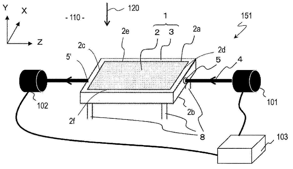
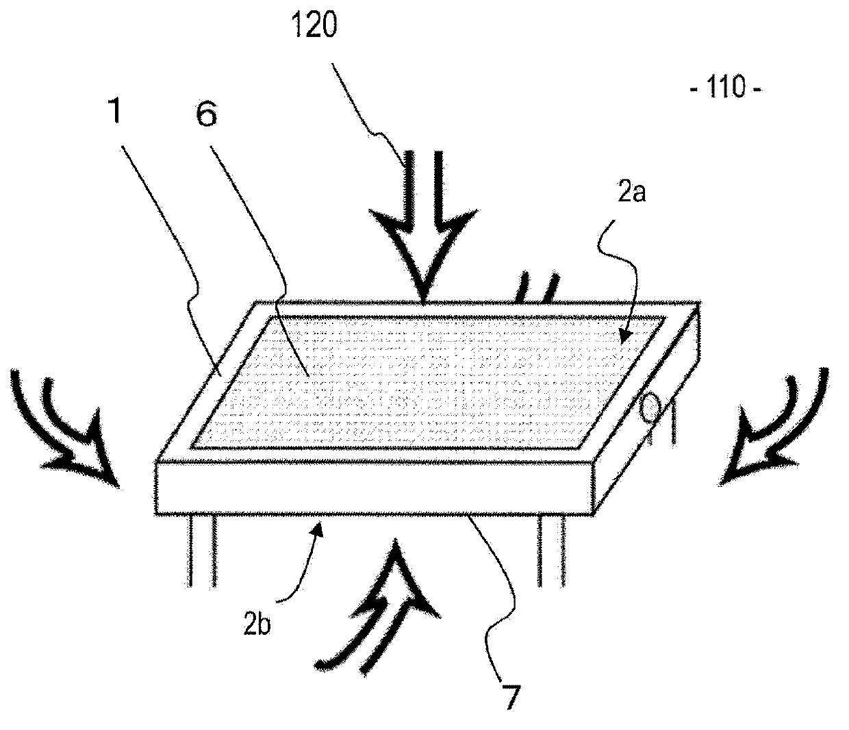
[0072] Hereinafter, the first embodiment of the optical microphone of the present invention will be described with reference to the drawings. figure 1 It schematically shows the configuration of the main part of the first embodiment of the optical microphone of the present invention. figure 1 The illustrated optical microphone 151 includes the following: a sound receiving section 1 including an acousto-optic medium section 2 and a restraining section 3; and a light emitting section 101. The light emitting unit 101 and the light receiving unit 102 constitute an optical interferometer 103 having a light emitting unit. The sound receiving unit 1 is in contact with the environmental fluid 110, and the sound wave 120 propagating in the environmental fluid 110 enters the sound receiving unit 1. The light wave 4 emitted from the light emitting unit 101 passes through the sound receiving unit 1. In the sound receiving section 1, since the optical path lengt...

Example

[0124] (Second embodiment)

[0125] Hereinafter, the second embodiment of the optical microphone of the present invention will be described with reference to the drawings. Figure 23 It schematically shows the configuration of the main part of the second embodiment of the optical microphone of the present invention. Same as the first embodiment, Figure 23 The illustrated optical microphone 152 includes a sound receiving unit 1 including an acousto-optic medium unit 2 and a restraining unit 3, and a light emitting unit 101. The light emitting unit 101 and the light receiving unit 102 constitute an optical interferometer 103. The sound receiving unit 1 is in contact with the environmental fluid 110, and the sound wave 120 propagating in the environmental fluid 110 enters the sound receiving unit 1. In the sound receiving section 1 through which the light wave 4 emitted from the light emitting section 101 passes through the sound receiving section 1, the optical path length of the...


PUM

PropertyMeasurementUnit
Sizeaaaaaaaaaa
Widthaaaaaaaaaa
Lengthaaaaaaaaaa

Abstract

An optical microphone includes: an acousto-optic medium section having a pair of principal surfaces and at least one lateral surface provided therebetween; a restraint section which is in contact with the at least one lateral surface for preventing a shape change of the acousto-optic medium section; and a light emitting section for emitting a light wave so as to propagate through the acousto-optic medium section between the pair of principal surfaces. The pair of principal surfaces are in contact with an environmental fluid through which an acoustic wave to be detected is propagating and are capable of freely vibrating, and an optical path length variation of a light wave propagating through the acousto-optic medium section, which is caused by the acoustic wave that comes into the acousto-optic medium section from at least one of the pair of principal surfaces and propagates through the acousto-optic medium section, is detected.

Description

Technical field [0001] This application relates to an optical microphone that receives sound waves propagating in a gas such as air and sound waves propagating in a solid, and uses light waves to convert the received sound waves into electrical signals. Background technique [0002] As a device for detecting sound waves, a microphone has been known. Most microphones represented by dynamic microphones and condenser microphones use diaphragms. These microphones vibrate the vibrating membrane by the sound wave input, and extract the vibration as an electric signal through a piezoelectric effect and a change in electrostatic capacity. In addition, there is also known an optical microphone that detects the vibration of the diaphragm via light waves such as laser light. [0003] On the other hand, Patent Document 1 discloses an optical microphone that does not use a vibrating membrane but detects sound waves by light waves. Such as Figure 35 As shown, the optical microphone disclosed ...

Claims


Application Information

Patent Timeline
IPC IPC(8): H04R23/00
CPCH04R23/008H04R23/00Y10T428/24008
Inventor 岩本卓也横山和夫桥本雅彦寒川潮金子由利子
Owner PANASONIC CORP
Why Eureka
Try Eureka