Cable lock

a cable lock and cable technology, applied in the field of cable locks, can solve the problems of reducing the size of the closed loop when the cable lock is in the locked condition, affecting the value of articles, and the belt or the lock body may damage the locked article, etc., and achieve the effect of not being able to reduce or enlarged the size of the closed loop

Active Publication Date: 2006-09-12
SINOX CO LTD
View PDF10 Cites 49 Cited by
  • Summary
  • Abstract
  • Description
  • Claims
  • Application Information

AI Technical Summary

Benefits of technology

[0007]It is therefore a primary objective of the present invention to provide a cable lock wherein the size of the closed loop can be kept fixed after being locked. In addition, the lock body provides a slot that allows the extremity of the belt to be inserted easily, reducing the dexterity required by the user.
[0008]To achieve the aforementioned goals, an improved cable lock structure is provided in the present invention, including a lock body and a belt, a hole which is disposed on the lock body to allow the sliding and passing therethrough of the belt, and a slot disposed to a side of the lock body to allow the insertion of the belt extremity. The lock body has a combination lock mechanism, a first clamp member, and a second clamp member disposed thereon. After the adjustment of the size of the closed loop formed by the lock body together with the belt is complete, the first and the second clamp member are utilized respectively to provide a holding effect on the extremity of the belt inserted into the slot and on the part positioned inside the hole. Afterwards, the combination lock mechanism is then switched to a locked status to confine the positioning of the first and second clamp members so that the size of the closed loop cannot be reduced or enlarged.
[0010]In practice, the lock body of the cable lock according to the present invention can further include a key tube, a third clamp member, and a fourth clamp member to achieve the goal. Similarly, after the adjustment of the size of the closed loop formed by the lock body together with the belt is complete, the third and the fourth clamp members are utilized respectively to provide a holding effect on the extremity of the belt inserted into the slot and on the part positioned inside the hole. Afterwards, the combination lock mechanism is then switched to a locked status to confine the positioning of the third and fourth clamp members so that the size of the closed loop cannot be reduced or enlarged.

Problems solved by technology

In practice, the locked article may be damaged by the belt or the lock body, when the belt is pulled to make the size smaller.
As a result, the article can become damaged easily.
Thus, it can be seen that, the reducible size of the closed loop when the cable lock is in the locked condition is a drawback concerning articles of value.
It may be difficult for a user to apply the cable lock when such an accurate operation is required.

Method used


Image

  • Cable lock
  • Cable lock
  • Cable lock

Examples


Embodiment Construction

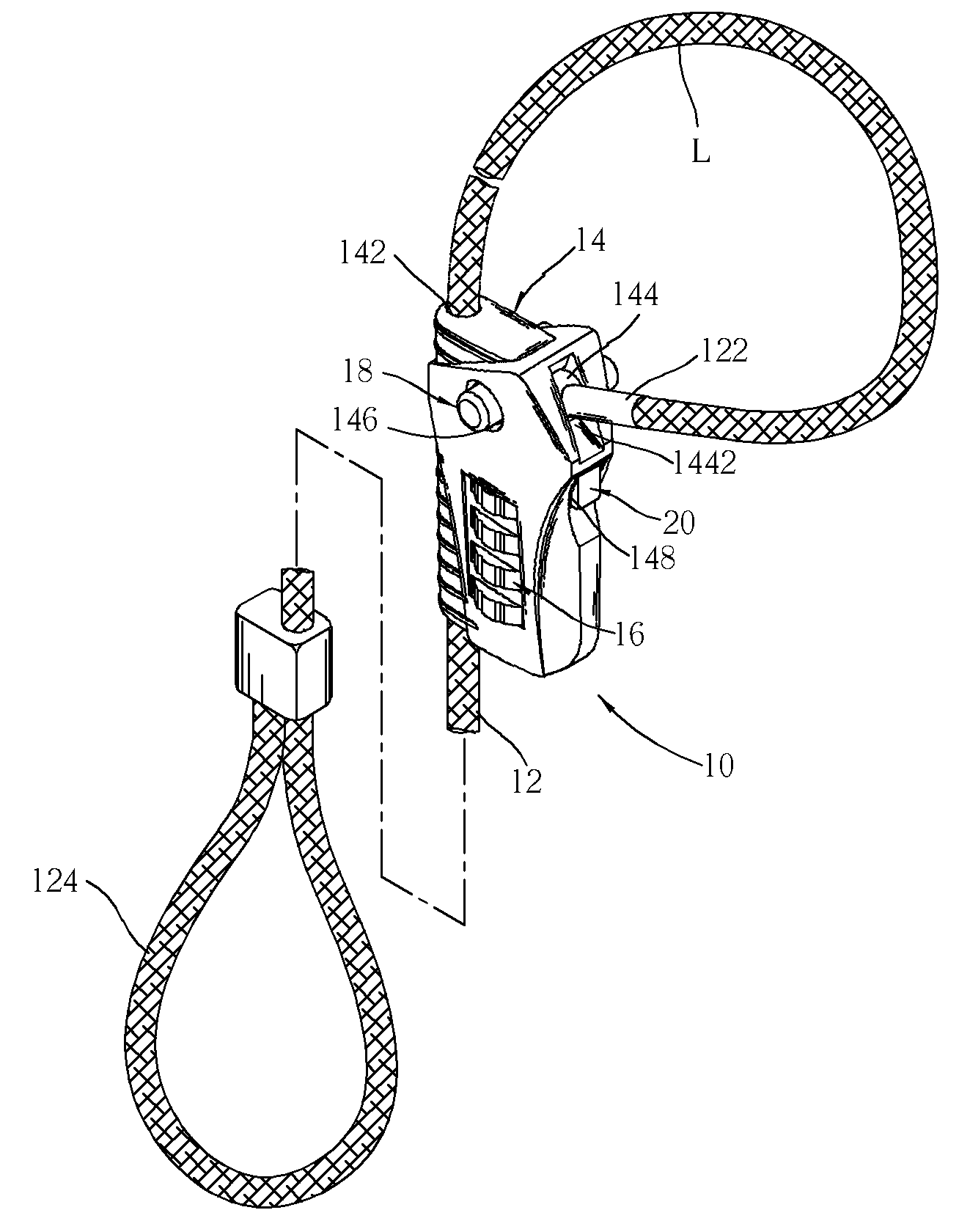
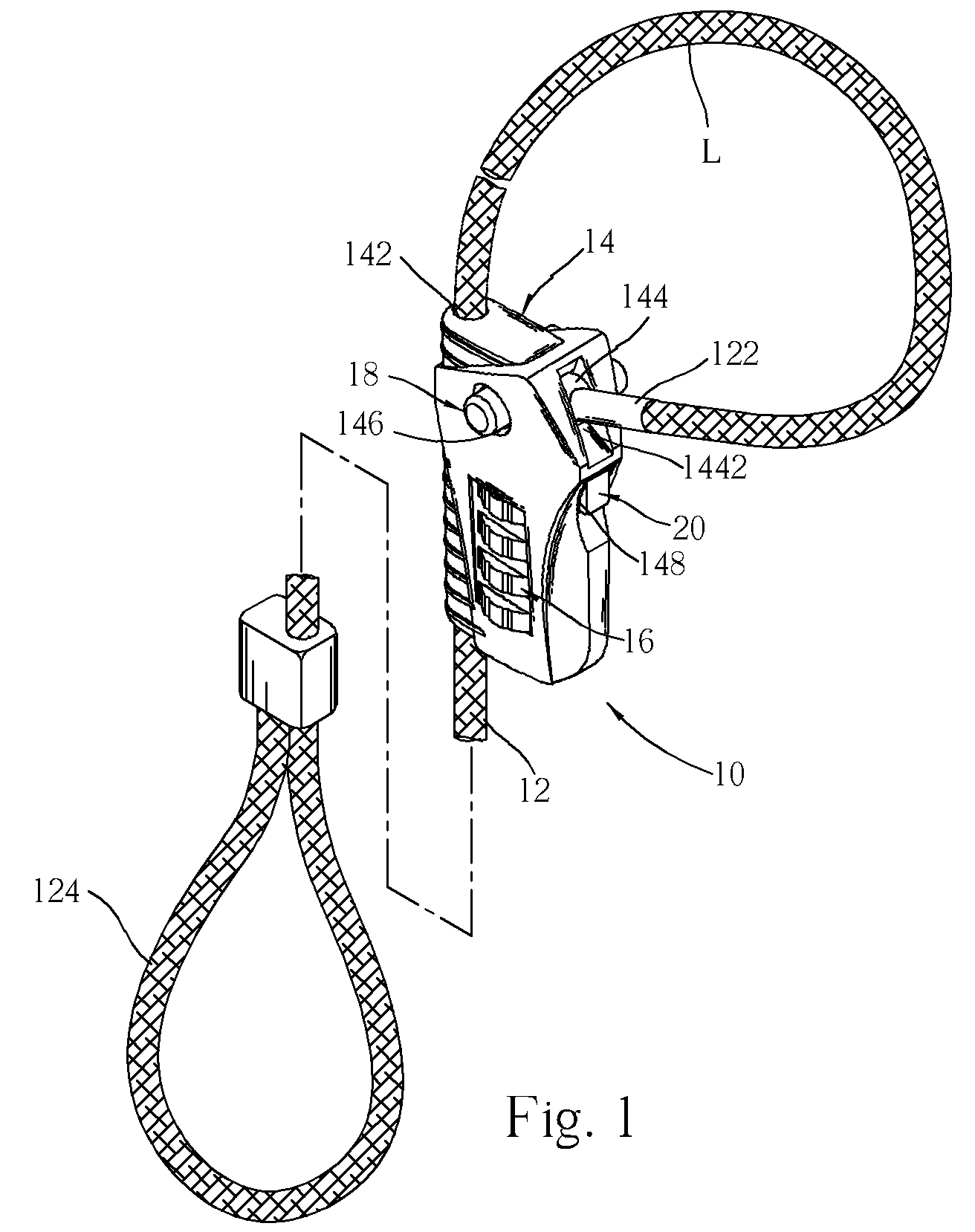
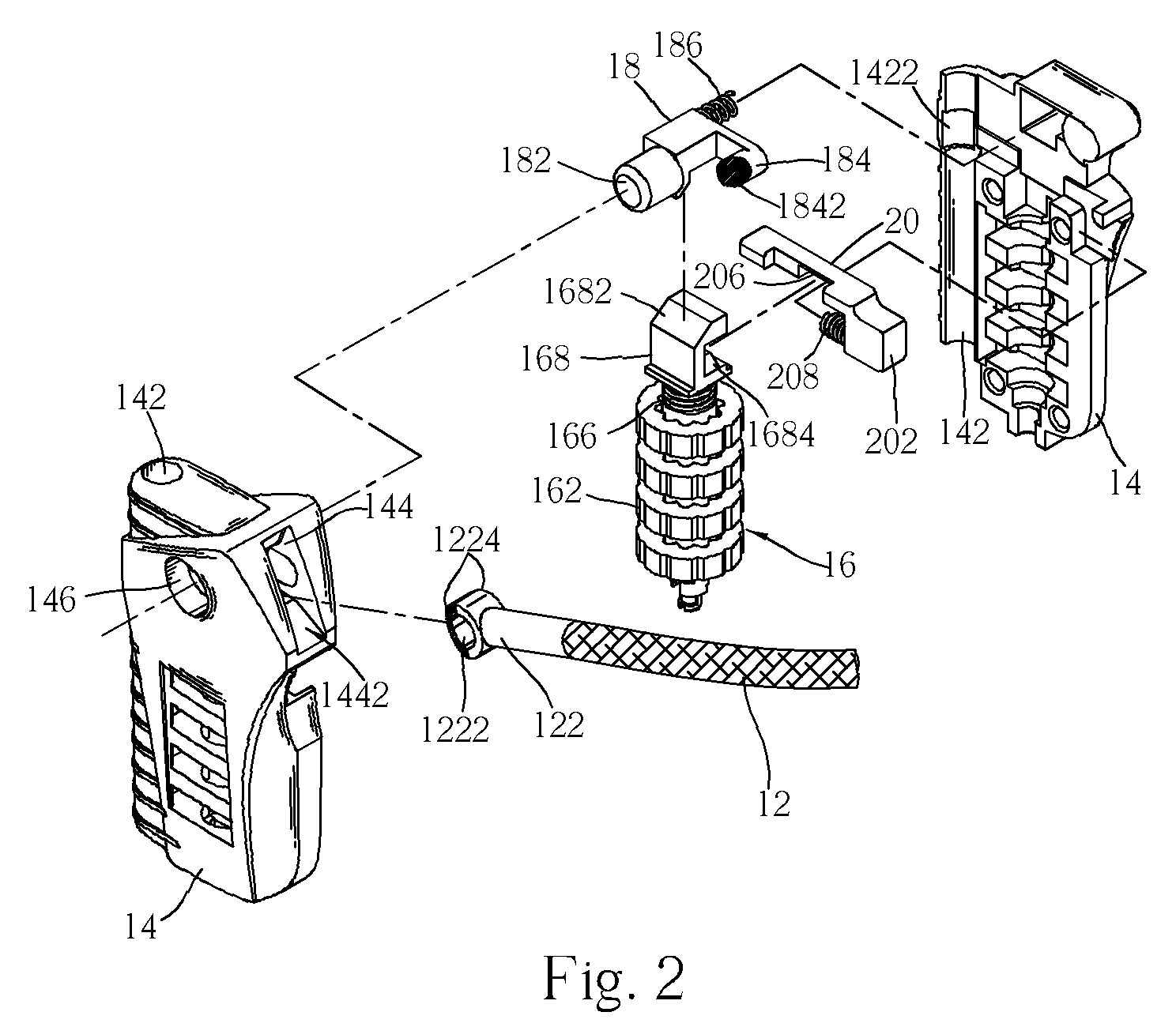
[0023]Please refer to FIG. 1 to FIG. 3. The cable lock 10 according to the present invention includes a belt 12, a lock body 14, a combination lock mechanism 16 positioned on the belt 12, a first clamp member 18 and a second clamp member 20. The characteristics and relationship between each member are described as follows.

[0024]The belt 12 can be, but is not limited to, a cable or a steel rope with suitable length and flexibility. A buckle member 122 is disposed at an extremity of the cable while a ring 124 is disposed at the other extremity so that the belt 12 can be secured on a fixed article. The lock body 14 can include a plurality of shell bodies, and has a hole 142 disposed at a lateral side thereof to allow the sliding and passing therethrough of the belt 12, and a slot 144 positioned at another side for supporting the insertion of the buckle member 122 so that the belt 12 together with the lock body 14 are allowed to constitute a closed loop L.

[0025]The combination lock mech...


PUM


Abstract

A cable lock includes a lock body and a belt which constitutes a closed loop. The closed loop is adjustable when the lock body is in an unlock condition. When the lock body is switched to a lock condition, the belt is restricted so that the closed loop is not adjustable.

Description

BACKGROUND OF INVENTION[0001]1. Field of the Invention[0002]The present invention relates to a cable lock that includes an adjustable closed loop. The cable lock secures an object by virtue of looping the object and adjusting the size of the closed loop where necessary.[0003]2. Description of the Prior Art[0004]U.S. Pat. No. 6,470,718 (denoted as '718) to Yang describes a cable lock composed mainly of a belt and a lock body. The belt can pass through the interior of the lock body, which is in connection to an end of the belt, to form a closed loop to be secured on an article. After adjusting the size of the closed loop to prevent the release of the locked article, the belt is then locked by the lock body and makes it be secured by the cable lock.[0005]According to the structure of the cable lock disclosed in the '718 patent, when the adjustment of the size of the closed loop is completed and a locked condition is reached, the belt can be pulled along a direction to reduce the size o...

Claims


Application Information

Patent Timeline
Patent Type & Authority Patents(United States)
IPC IPC(8): E05B37/02E05B71/00E05B71/02E05B73/00
CPCE05B73/0005E05B71/00Y10T70/424Y10T70/7305Y10T70/5009Y10T70/435
Inventor LING, RENNY TSE-HAWYU, CHANG-CHIANG
Owner SINOX CO LTD
Why Eureka
Try Eureka