Heat dissipating microdevice

a micro-device and heat dissipation technology, applied in the direction of fluid speed measurement, insulated cables, insulated conductors, etc., can solve the problem of not being suitable for heat dissipation applications

Active Publication Date: 2006-09-19
ASIA VITAL COMPONENTS SHENZHEN CO LTD
View PDF13 Cites 37 Cited by
  • Summary
  • Abstract
  • Description
  • Claims
  • Application Information

AI Technical Summary

Problems solved by technology

Although the method proposed therein permits hollow microstructure fabrication, since the resulting hollow microstructure is disposed in between the insulator layers, it is not suitable for heat dissipating applications.

Method used


Image

  • Heat dissipating microdevice
  • Heat dissipating microdevice
  • Heat dissipating microdevice

Examples


Embodiment Construction

[0034]Before the present invention is described in greater detail, it should be noted that like elements are denoted by the same reference numerals throughout the disclosure.

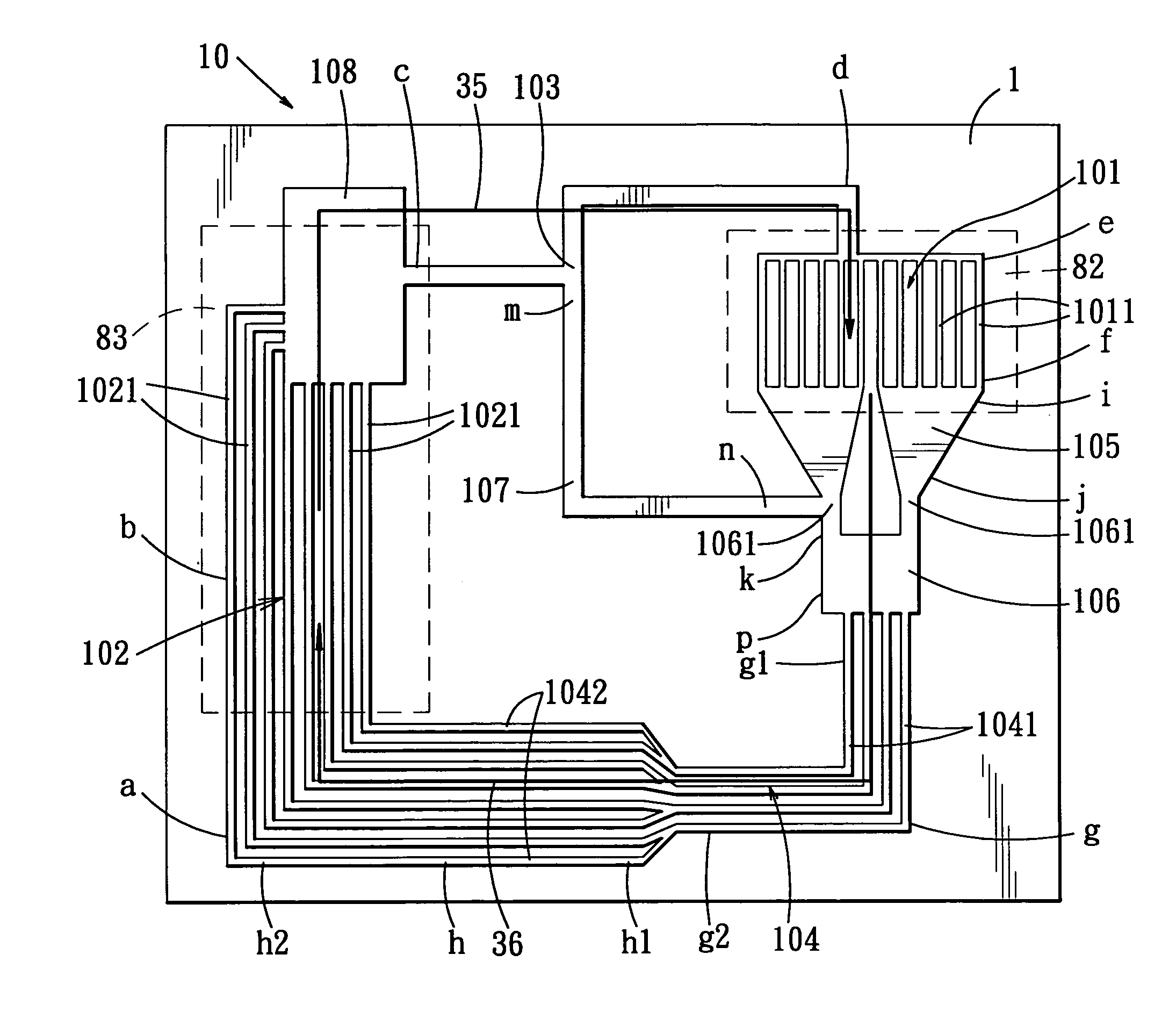
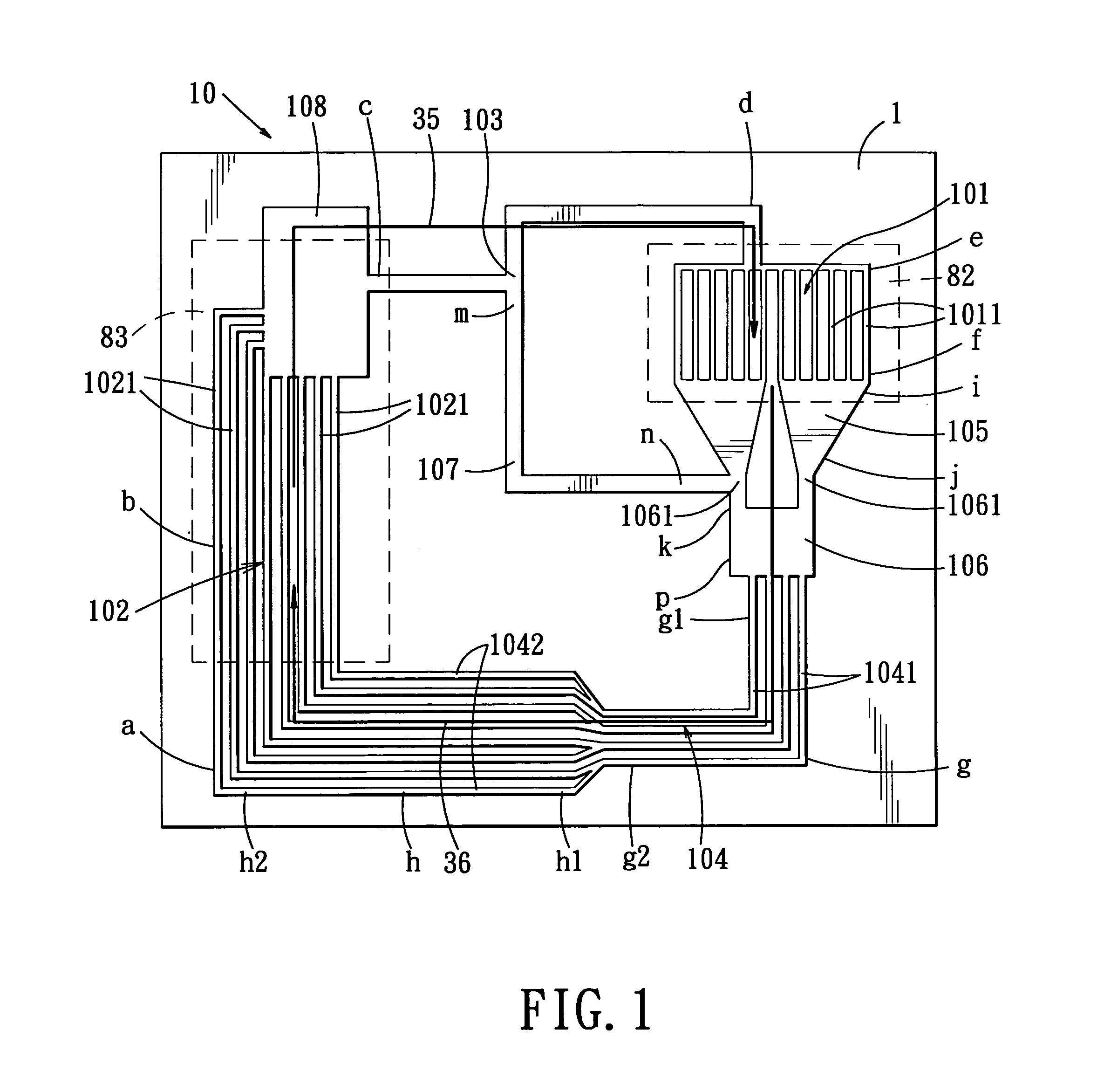
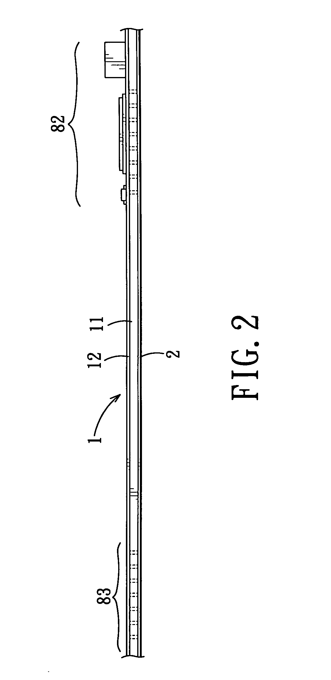
[0035]Referring to FIGS. 1 and 2, the first preferred embodiment of a heat dissipating microdevice according to this invention is shown to include a board 1, a fluid microsystem 10, and a coolant.

[0036]The board 1 includes a first insulator layer 11 that has a first surface and a second surface opposite to the first surface in a first direction, a first conductor layer 12 formed on the first surface, and a cover member 2 disposed on the second surface. The board 1 has a first area 82 and a second area 83 opposite to the first area 82 in a second direction transverse to the first direction. The first area 82 is adapted to be placed in thermal contact with a heat source (not shown). Preferably, the first insulator layer 11 is made from epoxy resin. Moreover, the cover member 2 is preferably made of a material the ...


PUM


Abstract

A heat dissipating microdevice includes a board, a fluid microsystem, and a coolant. The board includes an insulator layer that has first and second surfaces, a conductor layer formed on the first surface, and a cover member disposed on the second surface. The fluid microsystem is formed in the insulator layer of the board, and includes first and second micro-channel structures, and first and second micro-conduit structures that permit fluid communication between the first and second micro-channel structures. The coolant is contained in the fluid microsystem, and flows from the second micro-channel structure to the first micro-channel structure through the first micro-conduit structure, and from the first micro-channel structure back to the second micro-channel structure through the second micro-conduit structure.

Description

CROSS-REFERENCE TO RELATED APPLICATION[0001]This application claims priority of Taiwanese application no. 092118323, filed on Jul. 4, 2003.BACKGROUND OF THE INVENTION[0002]1. Field of the Invention[0003]The invention relates to a heat dissipating microdevice, more particularly to a heat dissipating microdevice including a fluid microsystem formed in a insulator layer of a board.[0004]2. Description of the Related Art[0005]In German Patent Nos. DE19739719 and DE19739722, there is disclosed a conventional method of making a hollow microstructure using first and second circuit boards. Each of the first and second circuit boards includes an insulator layer that has first and second surfaces, and a conductor layer formed on the first surface of the insulator layer. The method comprises the steps of forming recesses in the conductor layer of the first circuit board and bonding the second surface of the insulator layer of the second circuit board on the conductor layer of the first circuit...

Claims


Application Information

Patent Timeline
Patent Type & Authority Patents(United States)
IPC IPC(8): H05K7/20B81B1/00F25D17/02F28D15/02H01L23/473H05K1/02
CPCF28D15/0266H01L23/473H05K1/0272F28D2015/0225F28F2210/02H01L2924/0002H01L2924/00H05K7/20
Inventor DING, PEI-PEILEE, CHANG-CHILIN, JAO-CHING
Owner ASIA VITAL COMPONENTS SHENZHEN CO LTD
Why Eureka
Try Eureka