Feeder assembly for particle blast system

a particle blast system and feeder technology, applied in the field of particle blast systems, can solve the problems of resisting torque, affecting the size and wear of the motor,

Inactive Publication Date: 2006-09-26
COLD JET
View PDF51 Cites 48 Cited by
  • Summary
  • Abstract
  • Description
  • Claims
  • Application Information

AI Technical Summary

Problems solved by technology

The seal force results in seal drag, creating a resisting torque which has to be overcome by the motor.
When the torque is present at the time the rotor is started turning, a substantial start up lo...

Method used


Image

  • Feeder assembly for particle blast system
  • Feeder assembly for particle blast system
  • Feeder assembly for particle blast system

Examples


Embodiment Construction

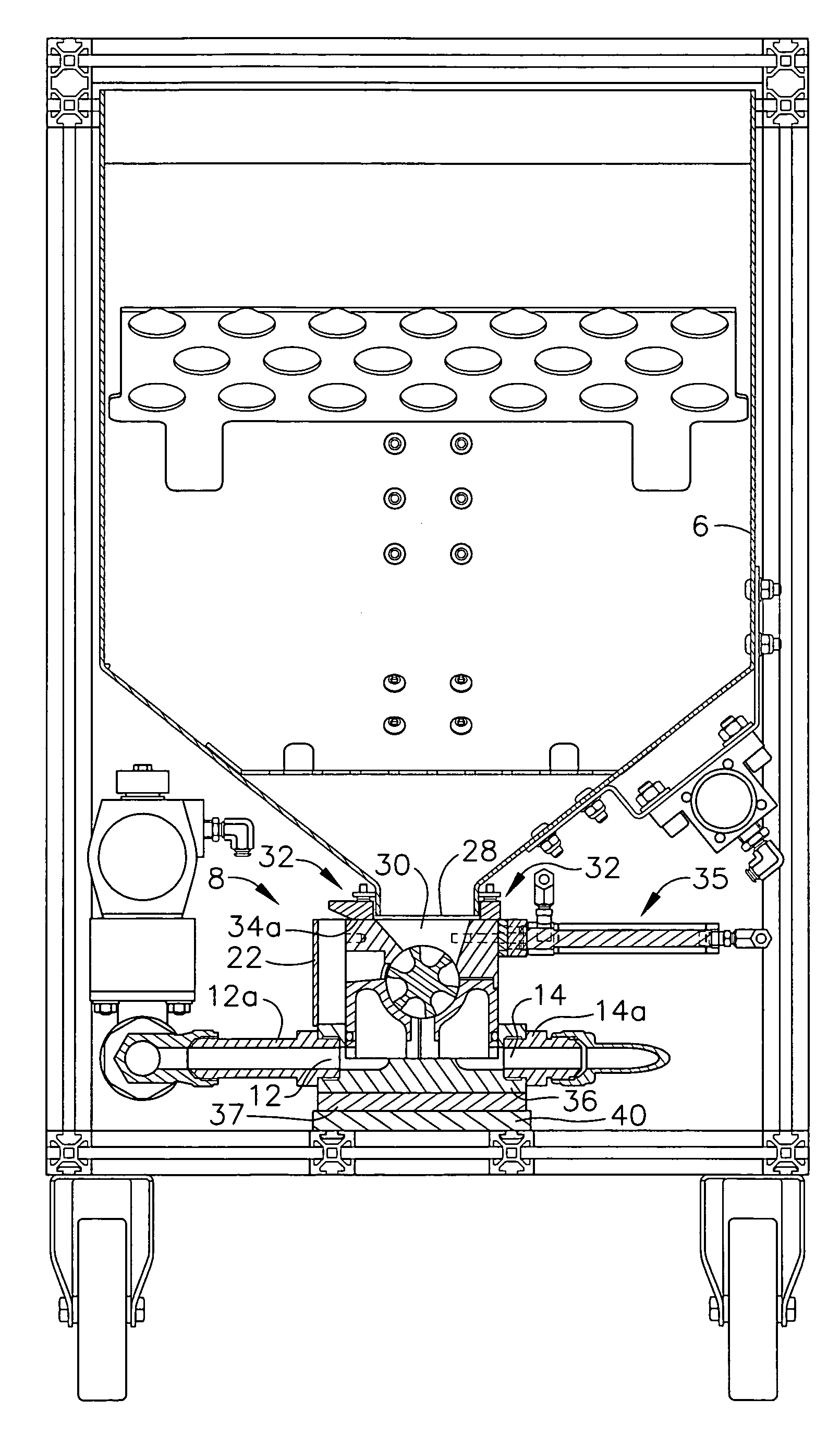
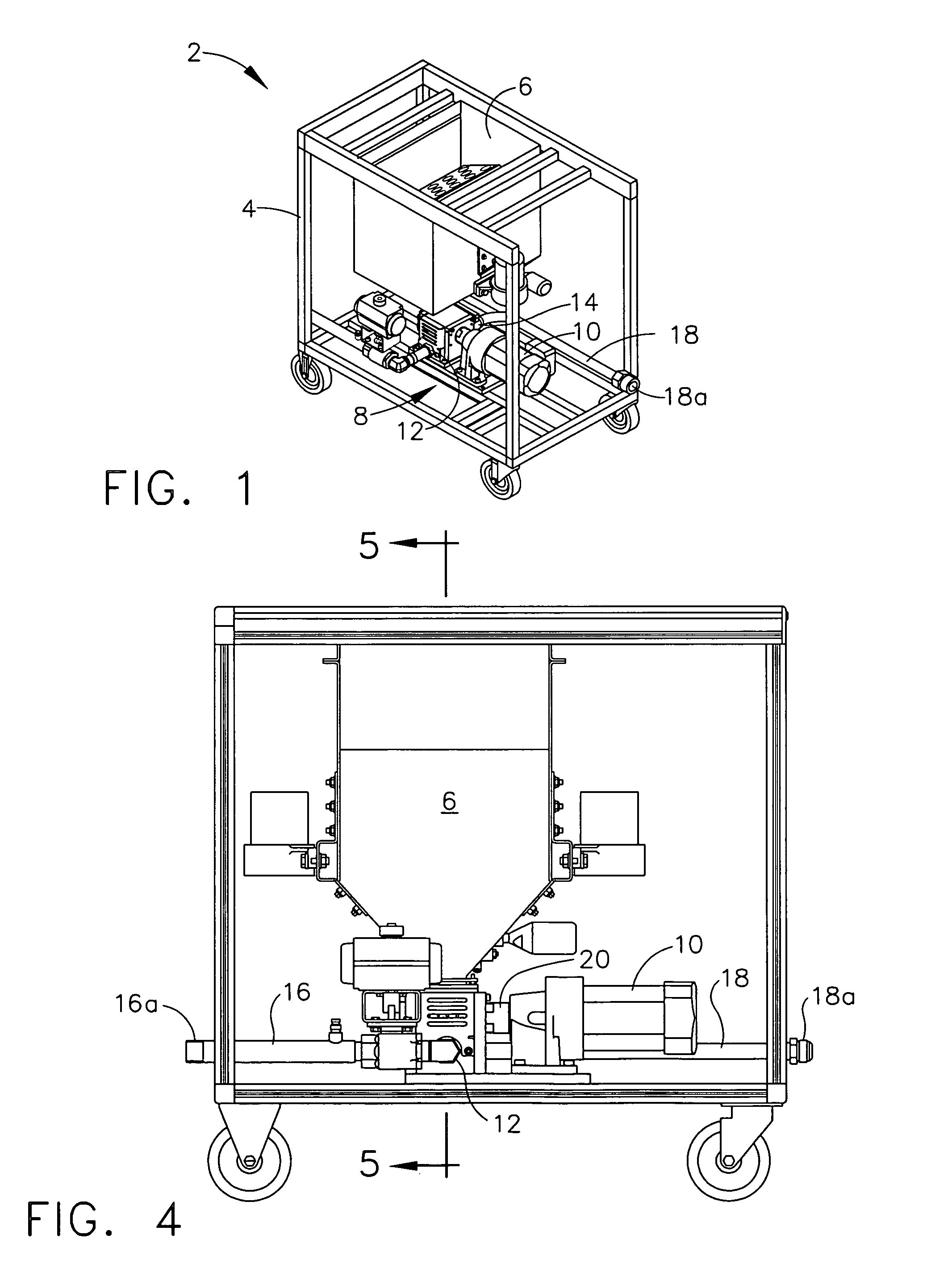
[0027]Referring now to the drawings in detail, wherein like numerals indicate the same elements throughout the views, FIG. 1 shows particle blast system, generally indicated at 2, with the outside cover omitted for clarity. Particle blast system 2 includes frame 4 which supports the various components. Particle blast system 2 includes hopper 6, which holds the blast media (not shown), functioning as a source of blast media. In the embodiment depicted, particle blast system 2 is configured to use sublimeable particles, particularly carbon dioxide pellets, as the blast media. It is noted that the present invention may be used with a wide variety of blast media, including non-cryogenic blast media.

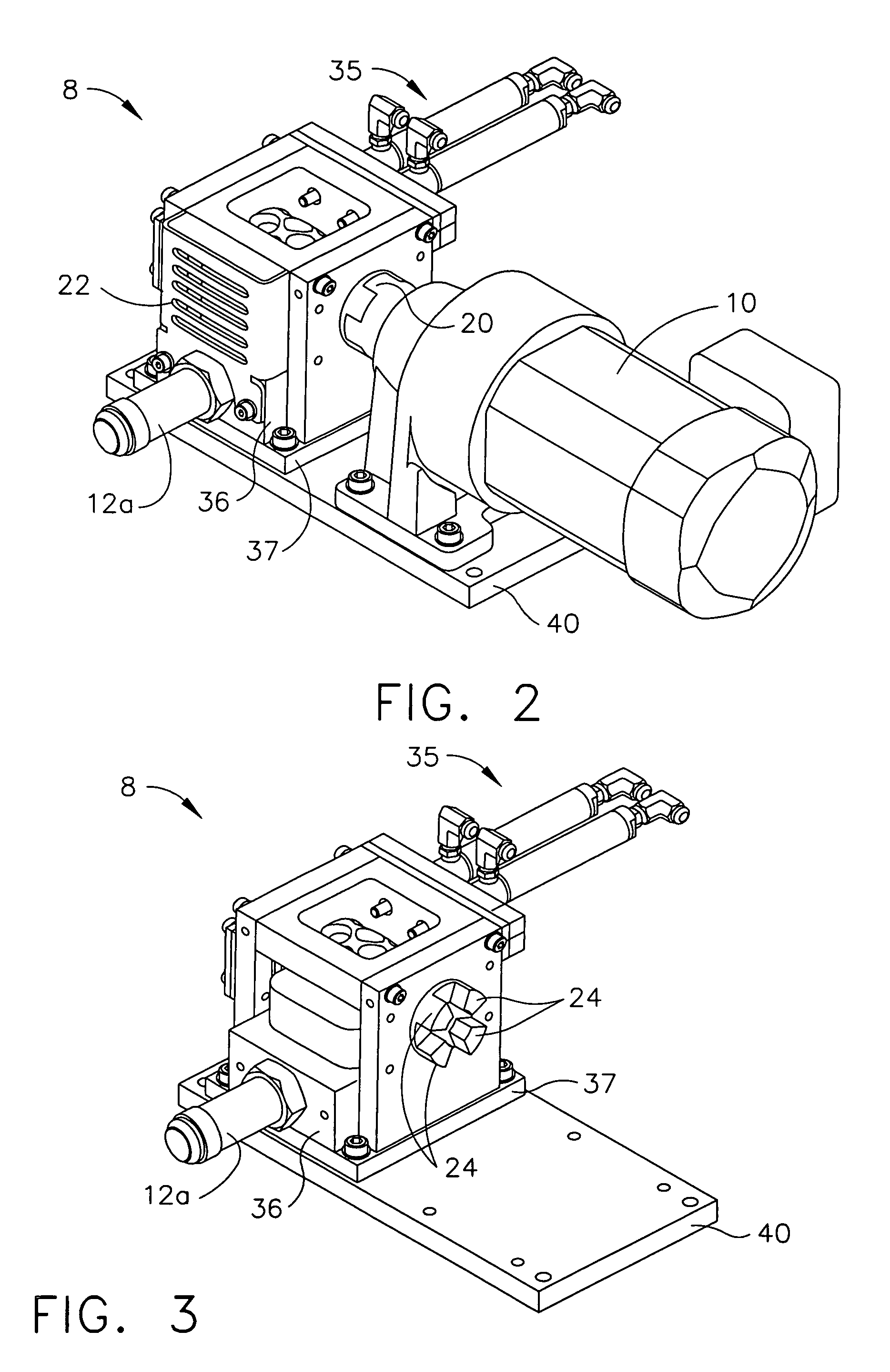
[0028]Particle blast system 2 includes feeder assembly 8, also referred to as the feeder, which is driven by motor 10. Feeder 8 includes inlet 12 and outlet 14. A transport gas flowpath is formed within feeder 8 between inlet 12 and outlet 14 (not seen in FIG. 1) as described hereinafter. Inl...


PUM

PropertyMeasurementUnit
Timeaaaaaaaaaa
Angleaaaaaaaaaa
Forceaaaaaaaaaa

Abstract

A particle blast system includes a feeder assembly having a rotor with a plurality of pockets formed in the peripheral surface. The transport gas flowpath includes the pockets, such that substantially all transport gas flows through the pockets. The seal adjacent the peripheral surface is actuated by the transport gas pressure to urge its sealing surface against the rotor's peripheral surface. At start up, there is no substantial pressure between the seal and the rotor, reducing start up torque requirements.

Description

BACKGROUND OF THE INVENTION[0001]The present invention relates generally to particle blast systems, and is particularly directed to a device which provides improved introduction of particles into a transport gas flow for ultimate delivery as entrained particles to a workpiece or other target. The invention will be specifically disclosed in connection with a transport mechanism in a cryogenic particle blast system which introduces particles from a source of such particles, such as a hopper, into the transport gas flow.[0002]Particle blasting systems have been around for several decades. Typically, particles, also known as blast media, are fed into a transport gas flow and are transported as entrained particles to a blast nozzle, from which the particles exit, being directed toward a workpiece or other target.[0003]Carbon dioxide blasting systems are well known, and along with various associated component parts, are shown in U.S. Pat. Nos. 4,744,181, 4,843,770, 4,947,592, 5,050,805, 5...

Claims


Application Information

Patent Timeline
IPC IPC(8): B24B1/00B24C1/00B24C7/00B65G53/46
CPCB24C1/003B65G53/4641B65G53/4633B24C7/0069B24C7/0046B65G53/4608
Inventor RIVIR, MICHAEL E.MALLALEY, DANIELBROECKER, RICHARD J.DRESSMAN, R. KEVINALFORD, KEVIN P.
Owner COLD JET
Why Eureka
Try Eureka