
Mounting bracket for power supply

a technology for mounting brackets and power supplies, applied in the field of mounting brackets, can solve the problems of increasing costs, adding extra components, undue laborious assembly process, etc., and achieve the effect of convenient and secure mounting of different types

Inactive Publication Date: 2006-09-26
HON HAI PRECISION IND CO LTD
View PDF3 Cites 8 Cited by
  • Summary
  • Abstract
  • Description
  • Claims
  • Application Information

AI Technical Summary

Benefits of technology

The present invention provides a mounting bracket that can easily and securely mount different types of power supplies to a computer enclosure. The mounting bracket has a body with countersunk portions that correspond to screw holes of the power supply, a fringe with an L-shaped latch for suspending on the enclosure, and tabs for engaging with the enclosure. The bracket also has spring fingers for electrically connecting with the enclosure. The technical effect of this invention is to provide a versatile and convenient solution for mounting power supplies to a computer enclosure.

Problems solved by technology

This makes the process of assembly unduly laborious and time-consuming.
However, manufacturing of such hinges adds extra components and increases costs.
In addition, it can be awkward and troublesome to attach a power supply to an enclosure using such hinges.

Method used


Image

  • Mounting bracket for power supply
  • Mounting bracket for power supply
  • Mounting bracket for power supply

Examples


Embodiment Construction

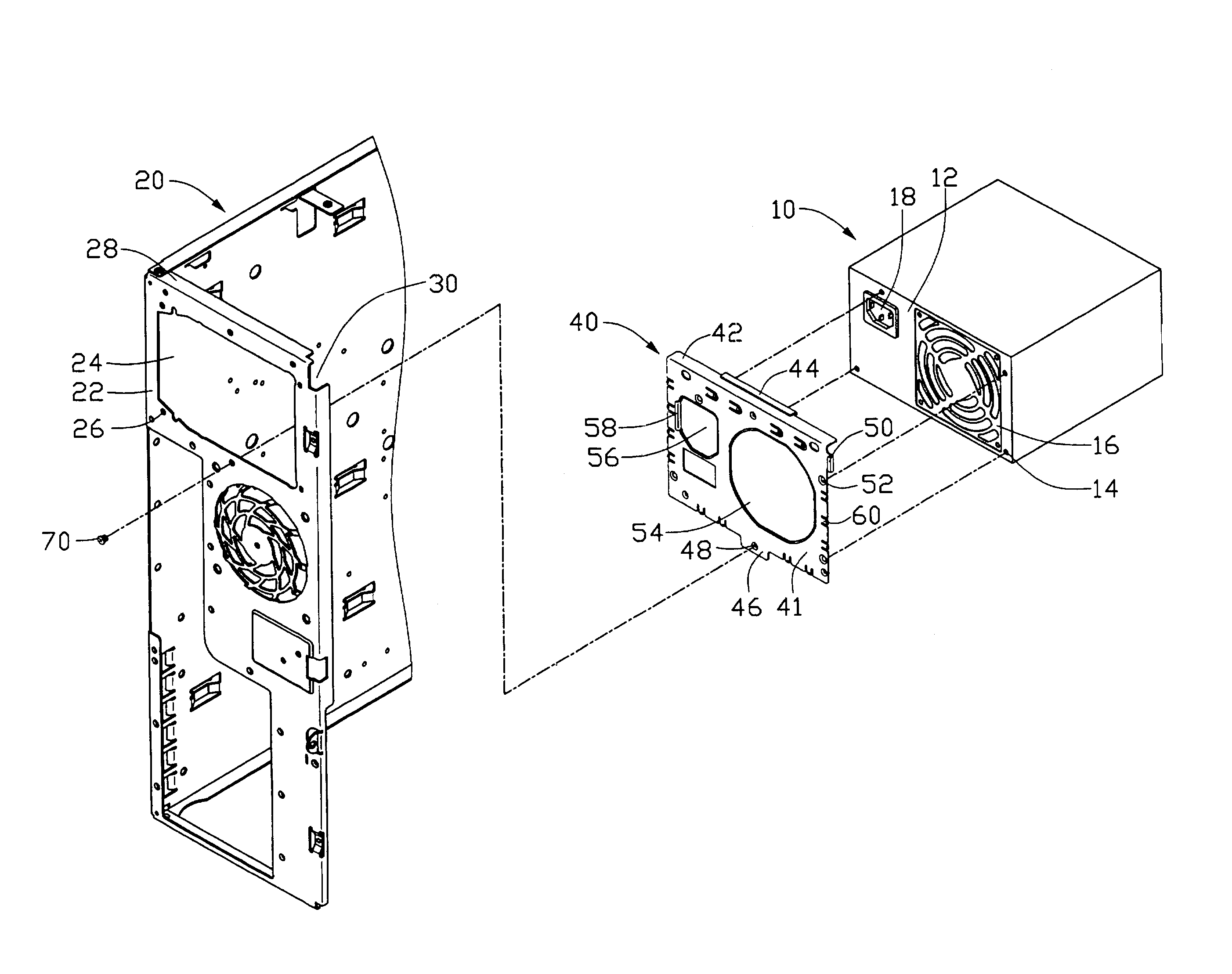
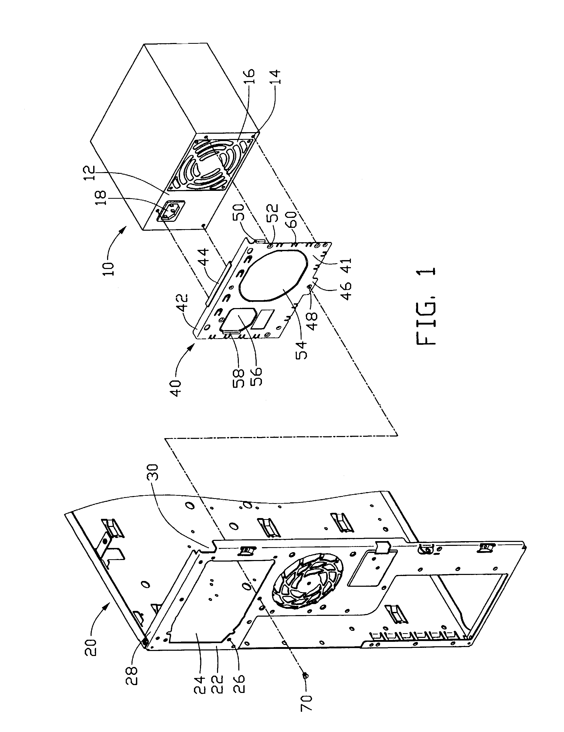
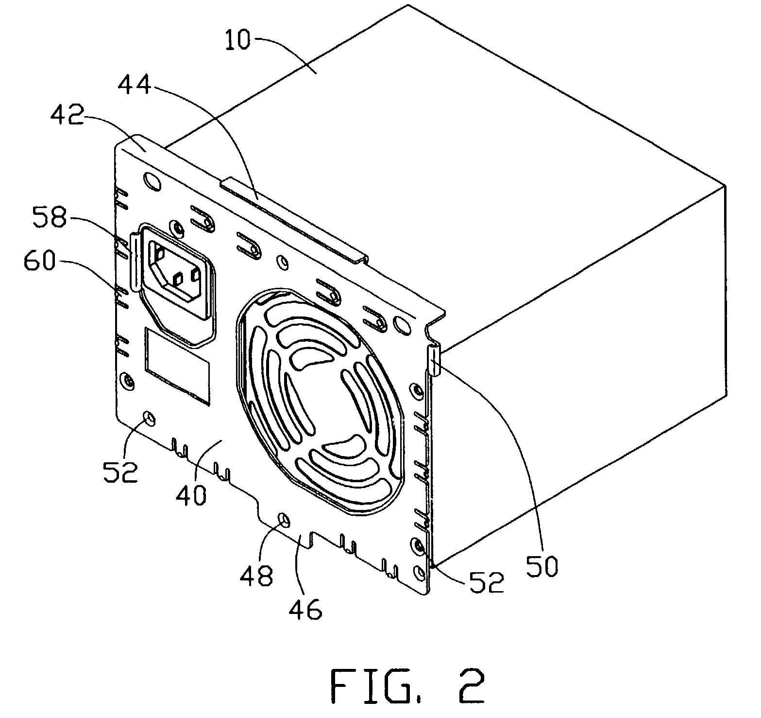
[0013]Referring to FIG. 1, a mounting bracket 40 in accordance with a preferred embodiment of the present invention is provided for attaching a power supply 10 to a computer enclosure 20. The power supply 10 comprises a rear surface 12. A plurality of screw holes 14 is defined in peripheral portions of the rear surface 12. A ventilating grille 16 for heat dissipation is defined in a right portion of the rear surface 12. A mains socket 18 is formed in a left portion of the rear surface 12.

[0014]The enclosure 20 comprises a rear panel 22. An opening 24 is defined in an upper portion of the rear panel 22, for exposing the power supply 10 to an exterior of the rear panel 22. A through hole 26 is defined in the rear panel 22 below a middle of the opening 24, for extension of a screw 70 therethrough to engage in the mounting bracket 40. A flange 28 is bent inwardly from a top edge portion of the rear panel 22. A gap 30 is defined in a junction of a top right corner of the rear panel 22 an...


PUM


Abstract

A mounting bracket (40) for mounting different types of power supplies (10) having different configurations of screw holes (14) to a computer enclosure (20) includes a body (41) for being attached to one of the power supplies. A plurality of countersunk portions (52) is defined in the body to configure such that selected of the through holes correspond to screw holes of the one of the power supplies. An L-shaped latch (44) is formed on a top portion of the body for suspending on the enclosure. A tab (46) depends from the body and defines a screw aperture (48) for engaging with a screw (60) which extends through the enclosure. A first rolled hook (50) and a second rolled hook (58) are formed outwardly from the body for engaging with the enclosure. A plurality of spring fingers (60) is formed in the body for electrically connecting with the enclosure.

Description

BACKGROUND OF THE INVENTION[0001]1. Field of the Invention[0002]The present invention relates to mounting brackets for attaching electronic components to equipment such as computer enclosures, and more particularly to a mounting bracket which can mount different types of power supplies having different configurations of screw holes.[0003]2. Description of the Related Art[0004]Many types of electronic equipment such as computer systems include power supplies which convert incoming alternating current to direct current. Direct current is suitable for operating various electrical components within such equipment. With the constant development of new electronic equipment, more and more components are required to be included within an electronic equipment enclosure. A power supply is generally one of the largest components in an electronic equipment enclosure. Thus the means of securing a power supply to electronic equipment determines the overall configuration of the equipment.[0005]A p...

Claims


Application Information

Patent Timeline
Patent Type & Authority Patents(United States)
IPC IPC(8): G06F1/16G06F1/18
CPCG06F1/184G06F1/188Y10T16/5367
Inventor CHEN, YUN LUNGSUN, DA-LONGTONG, LI
Owner HON HAI PRECISION IND CO LTD
Learn More