
Antenna apparatus for vehicle

a technology for vehicle antennas and antennas, which is applied in the direction of antennas, antenna details, antenna adaptation in movable bodies, etc., can solve the problems of difficult to receive radio waves, and large deviation of antenna length at the time of being mounted on the vehicle, so as to achieve convenient and secure mounting of antennas.

Inactive Publication Date: 2005-07-19
HARADA IND CO LTD +1
View PDF17 Cites 8 Cited by
  • Summary
  • Abstract
  • Description
  • Claims
  • Application Information

AI Technical Summary

Benefits of technology

[0025]This invention is made by taking the technical problems mentioned above into consideration, and one of basic objects of this invention is to provide an antenna apparatus for a vehicle which can improve a receiving performance of a radio wave having a short wavelength, and can restrict an influence of a noise. The other basic object of the present invention is to provide an antenna apparatus for a vehicle which can achieve a compatibility of a receiving sensitivity without causing a complex antenna structure and a special increase of a manufacturing cost, in the case of receiving a plurality of radio waves having different frequency by an antenna having a limited placing space.

Problems solved by technology

For example, the ideal antenna length for receiving the UHF is about 15 cm as mentioned above, however, an actual antenna length at a time of being mounted on the vehicle greatly deflects from this value.
Accordingly, it is hard to receive the radio wave having a short wavelength such as the UHF or the like, and in the worst case, there is a risk that it can not be received.
Accordingly, in the conventional art, with respect to receiving the radio wave having a high frequency, it is possible to correspond to the receipt by tuning in correspondence to a vehicle type, however, in order to obtain a good antenna characteristic, there is a problem that a lot of trouble is taken for tuning.
In this case, a pole antenna of the vehicle is of an earthed type, however, in this case, since a distance to the earthed vehicle body is very short, an influence of the other receivable portion than the antenna element is restricted minimum.
However, in this conventional structure, since the antenna element is provided dose to the earthed conductor on the part of the vehicle body such as a vehicle body member and a heating filament, there is a hard point that the antenna element is easily affected by a noise.
However, in the case that the antenna apparatus is provided in the inner portion of the vehicle body member mentioned above, it is generally hard to secure a proper antenna length, in connection to a limited space for arrangement.
However, in the antenna apparatus 80 shown in FIG. 12, there is a problem that a good receiving property is exhibited with respect to the FM (radio) broadcast wave, however, a sensitivity comes short with respect to the AM (radio) broadcast wave because the length of the antenna element is short.
Further, there is generated a problem that the receiving sensitivity with respect to the FM broadcast wave is reduced due to an impedance mismatch.
However, in this case, there are problems that an antenna structure becomes complex and a manufacturing cost becomes high.
The problem about compatibility in the receiving sensitivity as mentioned above is not limited to the case between the FM broadcast wave and the AM broadcast wave, but exists unavoidably in the case that one antenna receives a plurality of radio waves having different frequencies, for example, the case between the low band and the high band (VHF / High and Low) of the TV (television) broadcast wave or the like.

Method used


Image

  • Antenna apparatus for vehicle
  • Antenna apparatus for vehicle
  • Antenna apparatus for vehicle

Examples


Embodiment Construction

[0086]A description will be in detail given below of embodiments in accordance with the present invention with reference to the accompanying drawings.

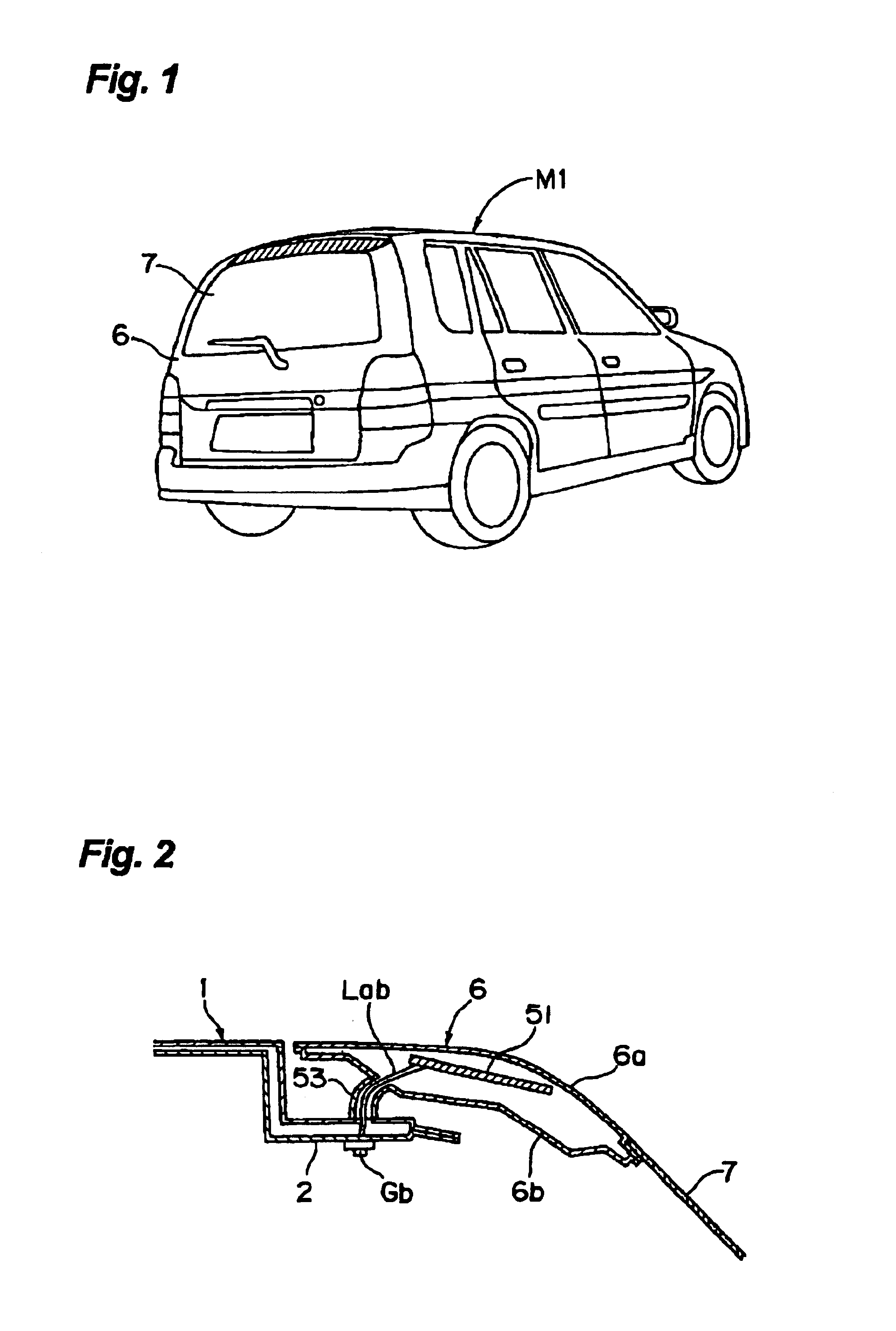
[0087]First, a description will be given of a first embodiment in accordance with the present invention. FIG. 1 is a perspective view showing a vehicle rear portion of a motor vehicle provided with an antenna apparatus for a vehicle in accordance with an example 1 of the present embodiment, and FIG. 2 is a vertical cross sectional explanatory view showing a mounting structure of the antenna for the vehicle to the vehicle (specifically, to a rear gate).

[0088]As shown in FIG. 1, in a motor vehicle M1 in accordance with the present embodiment, a rear gate 6 is provided as an opening and closing body for opening and closing an opening portion leaving a rear portion of a vehicle cabin open to a rear side, and an antenna is mounted to the rear gate 6. It is to be noted that, in FIG. 1, a position of an antenna mounting portion in the rear ga...


PUM


Abstract

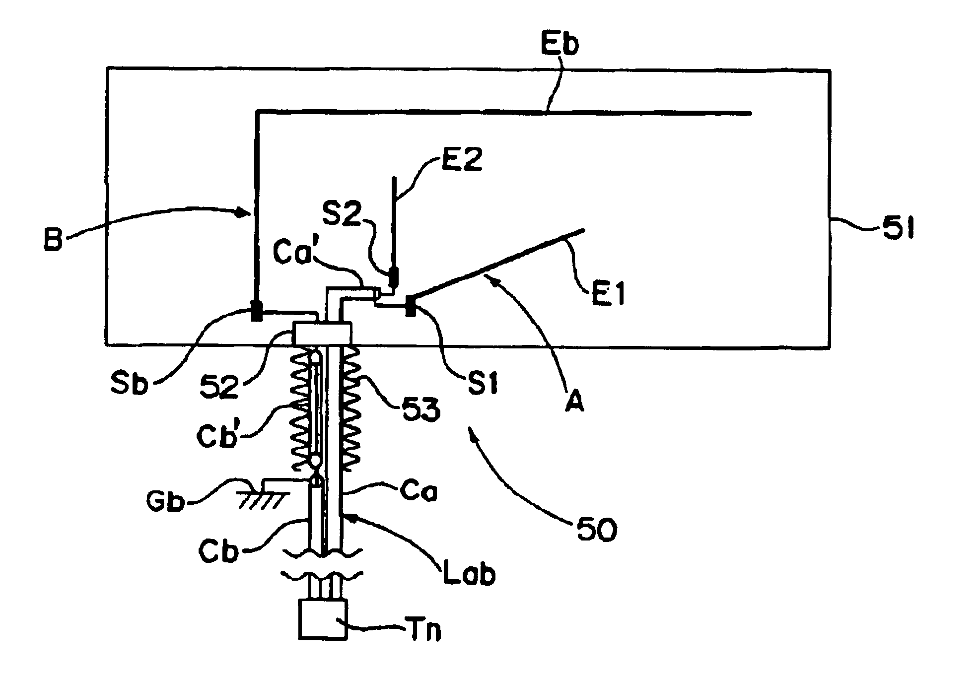
In an antenna apparatus for a vehicle, the antenna apparatus being provided on the vehicle in which at least a part of an outside plank panel of the vehicle is constituted by an outer panel made of a synthetic resin material, the antenna apparatus has at least one non-earthed type antenna, the non-earthed type antenna is provided with a first antenna element connected to an inner conductor of a coaxial cable via a first feeding point, and a second antenna element connected to an outer conductor of the coaxial cable via a second feeding point, and at least both the first and second antenna elements and both the first and second feeding points are arranged in a portion which is inside the outer panel made of the synthetic resin material and is apart from the earthed conductor on the part of the vehicle body, thereby it is possible to improve a receiving performance of a radio wave having a short wavelength, and can restrict an influence of a noise.

Description

BACKGROUND OF THE INVENTION[0001]1. Field of the Invention[0002]The present invention relates to an antenna apparatus for a vehicle, for example, mounted on a vehicle such as a motor vehicle or the like.[0003]2. Description of the Prior Art[0004]As an antenna apparatus provided in the vehicle such as a motor vehicle or the like, a so-called earthed type antenna is conventionally general In this earthed type antenna, a portion on and after a connection portion between a conductor of a coaxial line for the antenna and an earth wire, in other words, a portion from a branch point against the earth wire to a leading end of an antenna element, forms an actual receiver. That is, a receivable portion is provided in addition to the antenna element.[0005]In this case, as a subject to be received by the antenna apparatus for the vehicle, there can be listed up at least an AM radio broadcast wave, an FM radio broadcast wave, a TV broadcast wave and the like. Frequencies of these radio waves are...

Claims


Application Information

Patent Timeline
Patent Type & Authority Patents(United States)
IPC IPC(8): H01Q1/32H01Q1/12
CPCH01Q1/1271H01Q1/3275H01Q1/3283
Inventor ISHIBAYASHI, KATSUSHIROTANIGUCHI, TATSUAKISHIGETA, KAZUO
Owner HARADA IND CO LTD
Learn More