Wireless terminal

a wireless terminal and terminal technology, applied in the field of communication technology, can solve the problems of affecting the antenna reducing the radiation efficiency of the antenna, and impairing so as to enhance the radiation capability of the entire wireless terminal, enhance the electromagnetic radiation capability of the pcb, and improve the radio performance of the wireless terminal

Active Publication Date: 2016-04-05
HUAWEI DEVICE CO LTD
View PDF18 Cites 0 Cited by
  • Summary
  • Abstract
  • Description
  • Claims
  • Application Information

AI Technical Summary

Benefits of technology

[0005]Embodiments of the present invention provide a wireless terminal to improve radio performance of the wireless terminal.
[0008]As can be known from the technical solution, in the embodiments of the present invention, a groove is formed by cutting on the PCB to divide the PCB into two parts so as to produce a distributed capacitance effect and the connecting wires of the data connector may produce a distributed inductance effect, so that a resonant circulating current is formed. In this way, the radiation current on the entire PCB may be formed by two parts. One part is an excitation current generated by the antenna. The other part is a resonant circulating current generated by a resonant network including the connecting wires of the data connector, the second part of the PCB, the groove (equivalent to a capacitor with fixed capacitance), the first part of the PCB, and the metal casing of the data connector. Due to presence of the resonant circulating current, the electromagnetic radiation capability of the PCB is enhanced, and further the radiation capability of the entire wireless terminal is enhanced, so that the radio performance of the wireless terminal is improved, thereby effectively guaranteeing the radio performance of the wireless terminal in various application scenarios. In addition, the wireless terminal according to the embodiments of the present invention is easy to implement and has a low cost.

Problems solved by technology

However, when the wireless terminal rotates close to the terminal device, the antenna of the wireless terminal may be affected by the ground of the main board of the terminal device.
This decreases the radiation efficiency of the antenna and impairs the radio performance of the wireless terminal.

Method used


Image

  • Wireless terminal
  • Wireless terminal
  • Wireless terminal

Examples


first embodiment

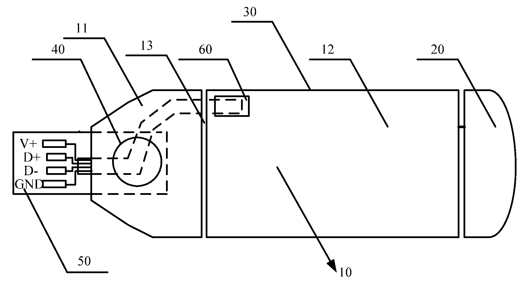
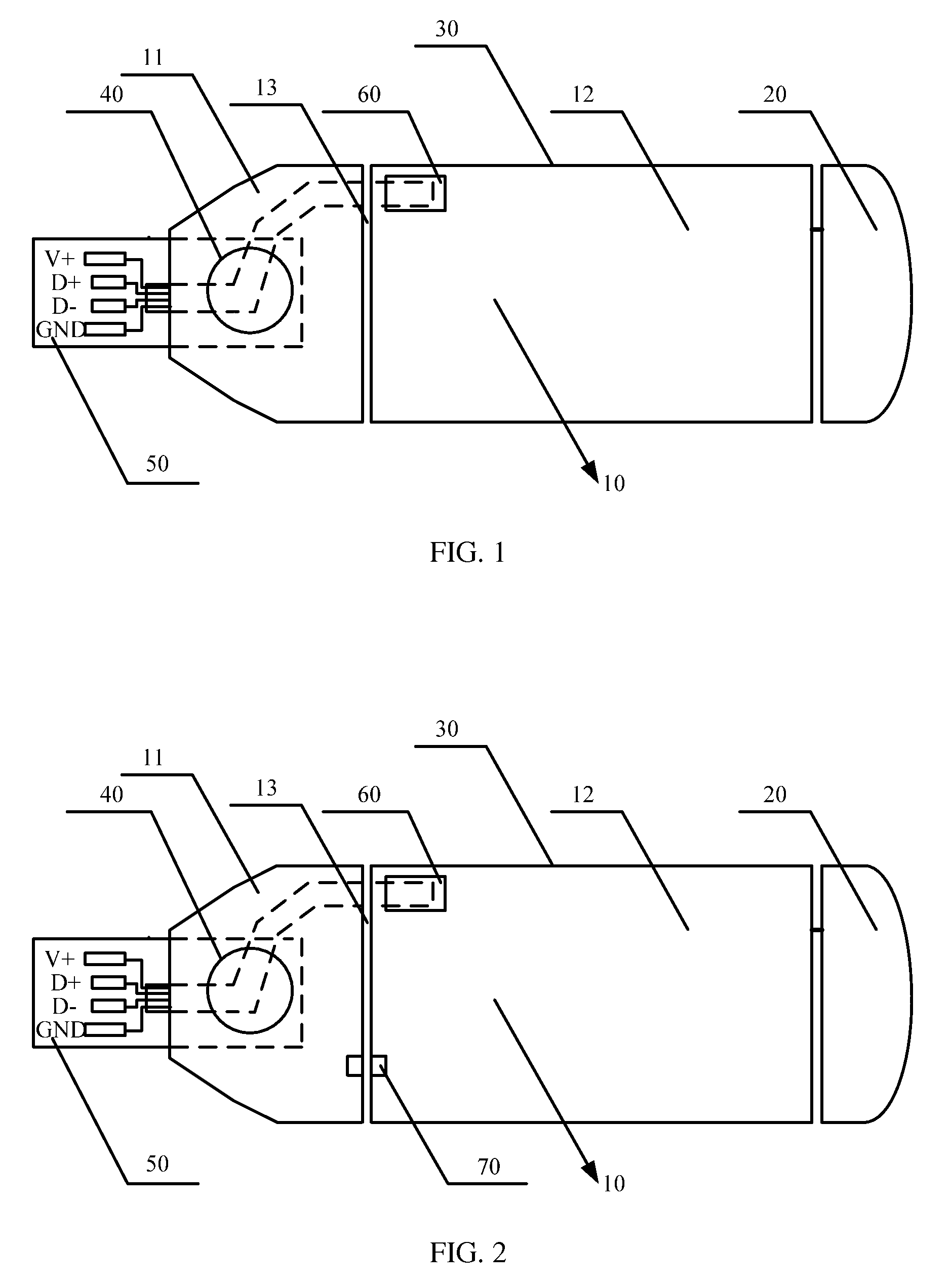
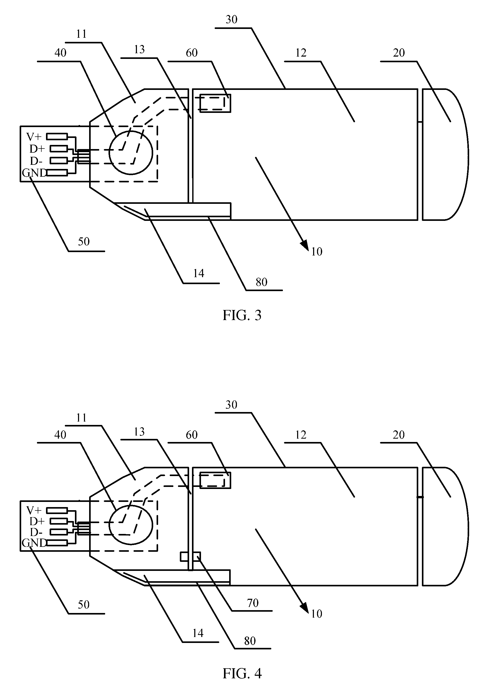
[0016]FIG. 1 is a schematic structural diagram of a wireless terminal according to the present invention. In this embodiment, the wireless terminal may include a printed circuit board (PCB) 10, an antenna 20, and a data connector 50, and may further include a casing 30. The PCB has a groove 13, which divides the PCB 10 into a first part 11 and a second part 12. The second part 12 is connected to the antenna 20, and the first part 11 is connected to the data connector 50 through a rotating shaft 40 (which may specifically be a piece of metalwork). Connecting wires of the data connector 50 (including a power wire, a ground wire, and a data wire) are connected to the second part 12 so that the connecting wires of the data connector 50, the second part 12, the groove 13, the first part 11, and the metal casing of the data connector 50 form a resonant network for generating a resonant circulating current. Particularly, the connecting wires (power wire V+, data wires D+ and D−, and ground...

second embodiment

[0021]FIG. 2 is a schematic structural diagram of a wireless terminal according to the present invention. The wireless terminal in this embodiment, based on the previous embodiment, may have a circuit network 70 loaded at the other end of the groove that is opposite to the cable pad 60. The circuit network 70 is connected to the ground of the first part 11 and the ground of the second part 12 respectively to establish a resonant connection between the metal casing of the USB connector and the second part 12 through the first part 11, so that the connecting wires of the data connector 50, the second part 12, the circuit network 70, and the metal casing of the data connector 50 form a resonant network for generating a resonant circulating current. As known by persons skilled in the art, the word “load” here refers to bridging two sides of the groove.

[0022]In particular, the circuit network in this embodiment may specifically be a resonant circuit, which may be formed by an inductor L ...


PUM


Abstract

Embodiments of the present invention provide a wireless terminal including a PCB, an antenna, and a data connector. The PCB has a groove, which divides the PCB into a first part and a second part. The second part is connected to the antenna, the first part is connected to the data connector through a rotating shaft, and connecting wires of the data connector are connected to the second part. The first part and the second part each have a ground. The ground of the first part is connected to a metal casing of the data connector and a ground wire of the data connector is connected to the ground of the second part and the ground wire of the data connector is electrically connected to the metal casing of the data connector.

Description

CROSS-REFERENCE TO RELATED APPLICATIONS[0001]This application is a continuation of International Application No. PCT / CN2012 / 070585, filed on Jan. 19, 2012, which claims priority to Chinese Patent Application No. 201110030267.1, filed with the Chinese Patent Office on Jan. 27, 2011, both of which are incorporated herein by references in their entireties.FIELD OF THE INVENTION[0002]Embodiments of the present invention relate to a communication technology, and in particular embodiments, to a wireless terminal.BACKGROUND OF THE INVENTION[0003]With the development of wireless communication technologies, more wireless terminals, such as data cards and M2M wireless modules, are emerging. A wireless terminal may be connected, by using a data connector (for example, a USB data connector) of the wireless terminal, through a port (for example, a USB port) of a terminal device (for example, a notebook computer), to the terminal device. In the prior art, the data connector of a wireless terminal...

Claims


Application Information

Patent Timeline
Patent Type & Authority Patents(United States)
IPC IPC(8): H01Q3/02H01Q3/04H04B1/3816H05K1/02
CPCH01Q3/04H04B1/3816H05K1/0227H05K2201/09972
Inventor XU, HUILIANGLAN, YAOSUN, SHUHUITU, DONGXINGWANG, DINGJIELEI, PINGSHUAI, PEIHUA
Owner HUAWEI DEVICE CO LTD
Why Eureka
Try Eureka